Advertisement
Quick Links
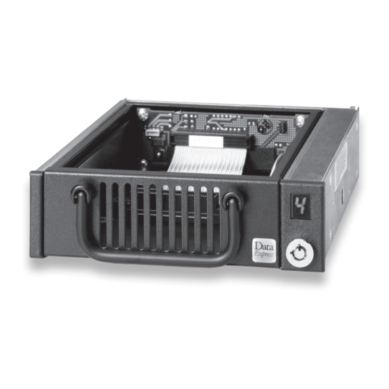
DE100 Ultra 160 68-pin Install Guide
Removable SCSI Wide Ultra160 Drive Enclosure
Figure 1: Drive Installation Assembly
Receiving Frame Motherboard
Factory-Installed Jumpers (J4): There are two (2) jumpers factory-in-
stalled on J4. One jumper is located on Pins 7 & 8, the other on Pins 9 & 10.
NOTE: Do not remove jumpers! (Remove only if attaching the 6103-
1020-0000 Isolator Board.)
Option Pin Connector (W1)
Remote Unit ID Selection: Pins 1-8 are provided for remote unit ID selec-
tion for the computer system or expansion chassis. Remote ID selection
requires that the unit ID select switch located inside the receiving frame be
set to "0".
Remote Activity LED: Pins 9 & 10 provide power for a remote LED device
activity indicator.
Enable Termination Power Connector (W2): A jumper is installed at the
factory and enables termination power to/from the SCSI bus.
NOTE: Do not remove this jumper!
Rugged, Reliable, Mobile, Secure
Figure 2: Drive Installation Assembly
Note: The DE100 Ultra 160 may be shipped with an isolator/repeater
board factory-installed. If this is the case, your DE100 Ultra 160 will
look slightly different from figure above. Please refer to figure below
for receiving frame with isolator/repeater board attached (rear view).
The DE100 Ultra 160 Isolator/Repeater Board is an upgrade attach-
ment for the DE100 Ultra 160 receiving frame. This attachment pro-
vides both an enhanced, bus-isolating hot swap and repeater function.
1-800-260-9800
www.CRU-DataPort.com
TM
Advertisement

Summary of Contents for CRU DE100 Ultra 160
- Page 1 Note: The DE100 Ultra 160 may be shipped with an isolator/repeater set to “0”. board factory-installed. If this is the case, your DE100 Ultra 160 will look slightly different from figure above. Please refer to figure below Remote Activity LED: Pins 9 & 10 provide power for a remote LED device for receiving frame with isolator/repeater board attached (rear view).
- Page 2 CRU product or service, even if CRU has been advised of the possibility of such damages. In no case shall CRU’s liability exceed the actual money paid for the products at issue.


Need help?
Do you have a question about the DE100 Ultra 160 and is the answer not in the manual?
Questions and answers