Subscribe to Our Youtube Channel
Summary of Contents for ICON Utrack
- Page 1 2-In / 2-Out Recording USB Interface with MIDI & S/PDIF I/O COMP DIRECT N16549...
- Page 2 Important Safety Instructions Read all manufacturer's warnings and instructions 2. Do not use this apparatus near water. 3. Clean only with dry cloth. 4. Do not block any ventilation openings and do not install near any heat sources such as radiators, heat registers, stoves, or other apparatus (including amplifiers) that produce heat.
-
Page 3: Table Of Contents
Contents Introduction What's in the package Features Front Panel Layout Rear Panel Layout Driver Installation Control Panel 8-10 11-12 Hardware Connections Minimum System Requirements Stacking the Utrack Specifications Services... -
Page 4: Introduction
Introduction Thank you for purchasing the ICON Utrack Digital Audio Interface. In these pages, you'll find a detailed description of all Utrack features, a guided tour through its front and rear panels, step-by-step instructions for its setup and use, and full specifications. -
Page 5: Features
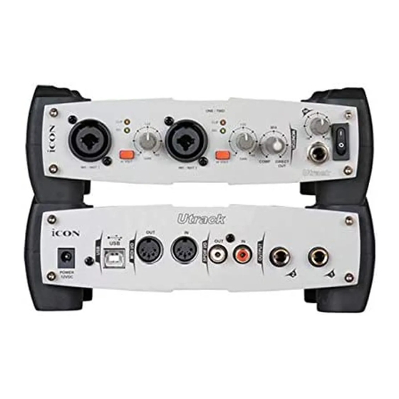
Features COMP DIRECT The ICON Utrack mobile interface audio input and output module offers USB connectivity. Main features include: 2 x 2 analog balanced I/O Dual microphone/instrument preamps with gain controls, LED metering, phantom power and input gain Two analog outputs on 1/4" TRS jacks S/PDIF I/O on RCA coaxial connectors Supports sampling rates from 44.1Hz to 192KHz... -
Page 6: Front Panel Layout
Front Panel Layout COMP DIRECT MIC/INST INPUTS Unbalanced Instrument and MIC level inputs. These hybrid connectors will accept a standard three-pin XLR plug or a 1/4" TS connector. CLIP LED When lit, this LED indicates clipping input level at the associated MIC/INST input. -
Page 7: Rear Panel Layout
S/PDIF COAXIAL IN AND OUT CONNECTORS S/PDIF digital input and output on coaxial RCA connectors. The digital input is selected via the Utrack's control panel, while the digital output will be sent to the coaxial . MIDI IN AND MIDI OUT CONNECTORS MIDI input and output on standard 5-pin DIN connectors. -
Page 8: Driver Installation
Driver Installation Please follow the below procedures step-by-step to install your Utrack and its driver. Turn on your computer Note: Do not connect the Utrack to your computer yet Insert Driver CD to your CD-Rom After you have insert the provided... - Page 9 Diagram5. Then click "Next". Diagram 5 Connect your Utrack Now, connect the Utrack to your computer's USB port and turn on its power switch and click "Finish". Notes: Utrack only support USB 2.0. Your computer must have an USB2.0 port.
- Page 10 Utrack's WDM driver installation has completed. Click "Finish" Diagram 11 Launch the Utrack Control Panel You may click the Utrack logo on the system tray to luanch the Utrack Contrl Panel (Page 8). Diagram 12 Note: For the latest driver updates please check www.icon-global.com...
-
Page 11: Control Panel
S/PDIF Status and Pass Through Showing the S/PDIF device signal staus. S/PDIF Pass Through "Tick" the box if you wanted S/PDIF signal pass through WDM Sound Device Configuration As Utrack is a 2x2 I/O interface, you Diagram 4 should select "Stereo" for this setting. - Page 12 Control Panel (Continues) Hardware Inputs Mixer Matrix Fader Hardware Inputs Ch1,2 & S/PDIF Level Metering Showing the input level for the hardware input channel. Hardware Onputs Ch1,2 & S/PDIF Level Metering Showing the output level for the hardware output channel. Link Switch Switch to adjust both Channels simutaneously Mute Switch...
- Page 13 Control Panel (Continues) Software Inputs Mixer Matrix Fader Software Inputs Ch1,2 & S/PDIF Level Metering Showing the input level for the software input channel. Software Onputs Ch1,2 & S/PDIF Level Metering Showing the output level for the software output channel. Link Switch Switch to adjust both Channels simutaneously Mute Switch...
-
Page 14: Hardware Connections
Hardware Connections Connect the Utrack's outputs to your amplifier, powered monitors or surround system. Two-channel stereo operation, the default outputs are channels 1 and 2. If you are monitoring through headphones, connect your headphones to the Utrack's headphone output. Connect your microphones, instruments or other line level analog sources to the Utrack's analog inputs. -
Page 15: Minimum System Requirements
Microsoft. On the Mac, the Utrack is supported under MacOS 9.2 or later, and Mac OSX version 10.1.5 or later. Earlier versions of Mac operating systems are not supported. -
Page 16: Stacking The Utrack
Stacking the Utrack You can stack one Utrack or any other ICON Neo Series gears on top of each other by simply lining up the bumpers. COMP DIRECT COMP DIRECT MIDI IN MIDI OUT SIGNAL CH 1 CH 2 CH 1... -
Page 17: Specifications
Specifications (Measured at 48KHz Sample Rate) Mic/Inst Inputs 1/2 (Balanced; at Minimum Gain): Frequency Response: 22Hz to 22kHz (+/-0.1dB) Dynamic Range: 100dB, A-weighted Signal-to-Noise Ratio: -100dB, A-weighted THD+N: <0.0061% (-90dB) Crosstalk: -100dB @ 1kHz Maximum Input level: -3.8dBu, typical Input Impedance: Inst in: 500K Ohms, typical;... -
Page 18: Services
ICON is not responsible for any damage that occurs due to non-factory packing. 3. Contact your ICON dealer or if none is available, contact the nearest ICON distributor or regional office to obtain a return authorization. If applicable, shipping instructions will be provided by the dealer or from ICON. - Page 19 UT PD3V100...


Need help?
Do you have a question about the Utrack and is the answer not in the manual?
Questions and answers