Table of Contents
Advertisement
Quick Links
• 12/24Vdc control board for one motor
• For Sliding gates, roll up doors, rolling shutters
• Connection with encoder
START-S7LT
Power supply of the accessories (max 1,6 A)
Power supply of the accessories (max 1,6 A)
Isolated contact for key lock or signal light
Isolated contact for key lock or signal light
- Antena / Com. contact for services and securities
+ 5Vdc power supply of the enCodeR
- power supply for enCodeR
Input for low TenSIon
Input for low TenSIon
Motor
Motor
Isolated contact for lamps
Isolated contact for lamps
-10-
-11-
SToP
-12-
PHoTo when closing
-13-
lSo
-14-
lSC
-15-
START
-16-
CloSe
-17-
-18-
+ Antena
-19-
-20-
Signal for enCodeR
-21-
RoHS
C O M P L I A N T
2002/95/eC
Manual and operating guide for the installer
-1-
-2-
-3-
-4-
-5-
-6-
-7-
-8-
-9-
n.o.
n.o.
*
MoT 1
Signal light
12/24 Vac/dc
*
*
n.C.
n.C.
n.C.
+ BAT
Fastom for the connection of the battery
- BAT
Power supply of the photo-beams:
Terminal Boards 5-6
Max absorption 1.6 A
Photocell
activated
when
closing
Advertisement
Table of Contents

Subscribe to Our Youtube Channel
Related Manuals for EB TECHNOLOGY Nologo START-S7LT


Summary of Contents for EB TECHNOLOGY Nologo START-S7LT
- Page 1 • 12/24Vdc control board for one motor • For Sliding gates, roll up doors, rolling shutters • Connection with encoder START-S7LT Manual and operating guide for the installer Input for low TenSIon Input for low TenSIon Motor Motor MoT 1 Power supply of the accessories (max 1,6 A) Power supply of the accessories (max 1,6 A) Signal light...
- Page 2 START-S7lT operating guide Index Premises This manual provides all the specific information you Par. Description Page need to familiarize yourself with and correctly ope- Introduction rate your unit. Read it very carefully when you pur- Safety precautions chase the instrument and consult it whenever you Symbols and warning have doubts regarding use and before performing Type of installation any maintenance operations.
-
Page 3: Type Of Installation
START-S7lT operating guide Introduction Safety precautions Using the unit improperly and performing repairs or modifications personally will void the warranty. The produ- cer declines any responsibility for damages due to inappropriate use of the product and due to any use other than the use the product was designed for. The producer declines any responsibility for consequential damages except civil liability for the products. -
Page 4: Description Of The Connections
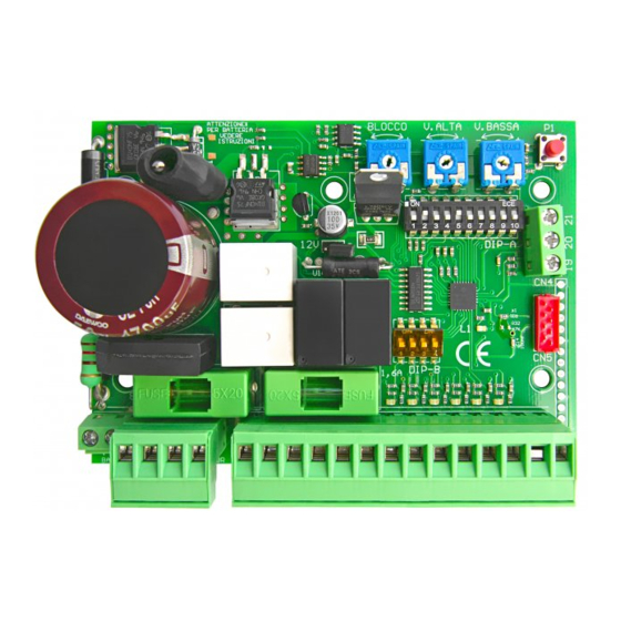
START-S7lT operating guide Description of the connections START-S7 lT is a new generation electronic circuit board with times count and digital deceleration. It has been built to meet many needs: for sliding gates, swinging and roller systems. Its reduced size makes it suitable for use it in all motors that are designed for internal electronics. -
Page 5: Notes On Connections
START-S7lT operating guide Premises Preliminary checks Making the correct choice of installation is essential to ensuring adequate safety and good protection against atmospheric agents. Remember that the control unit contains powered parts and electronic components which by their very nature are sensitive to infi ltrations and moisture. The control unit is supplied in a container which guarantees an IP55 protection rating if adequately installed. Install the control unit on a permanent surface that is perfectly flat, adequately protected against impacts and at least 40 cm off the ground. The cables must enter the control unit from the bottom only;... -
Page 6: Installation
START-S7lT operating guide Installation Scheme of the control unit and electrical connections correct cable to connect the battery and re- spect the polarity. + BAT DON’T CONNECT DIRECTLy J12V BATTERy. As the cable has a charge circuit, fuse and diode of power suplly. -
Page 7: Description Of The Electrical Connections
START-S7lT operating guide Description of the electrical connections 12/24 Vac/dc Input for low tension: set up the JUMPeR J12 Motor output for the connection of the MoToR - 12/24 Vdc output for the connection of the accessories: Absorption max 1.6 A + 12/24 Vdc i.c. -
Page 8: Connection Of The Motor
START-S7lT operating guide Connection of the POWER SUPPLy and BATTERy The following control board can be Use the correct cable to connect the powered 12/24Vac/dc. To set up battery and respect the polarity. DON’T the power supply put the jumper CONNECT DIRECTLy THE BATTERy. - Page 9 START-S7lT operating guide Connection of the LIGHT If you bring dIP8 in on you can connect a signa light which will be lit on before opening and two minutes after closing. DIP 8 - ON GRoUP oF lIGHT Besides the second channel of the remo- te control doesn’t close but it activate or deactivate the signal light.
- Page 10 START-S7lT operating guide 4.12 Connection of the Open and Close limt switches It is shown in the picture the connection of both limit switches: If the open and close limit switche are not used, bring DIP 3B in ON (open limit switch) and DIP 4B in ON The contacts of limit switches for close limit switch.
- Page 11 START-S7lT operating guide 4.14 Connection of the START commands The START command can be can be connected with each button or normally open contact to the terminal board no. 15-17 . If more devices are available, connect them in pa- rallel.
-
Page 13: Standard Function
START-S7lT operating guide Function The control unit START S7lT is for automatic doors, too. now we can see the correct installation. First of all there are two functions: STAndARd function and AUToMATIC dooR function. STANDARD FUNCTION AUTOMATIC DOOR FUNCTION (Default) Encoder Encoder The control unit opens and closes with an addi-... - Page 14 START-S7lT operating guide Logic of function DIPA The control unit has a number of micro-switches which activate different functions for a safety installation and suitable to the customer’s requirements: By every order it inverts: open and close. It clo- 1-oFF 2-oFF automatico ses automatically at the end of the pause time It doesn’t accept any order in pause and ope-...
- Page 15 START-S7lT operating guide Put in on to allow the input of the encoder. allow the 7-on In case it doesn’t connect, encoder input put the dip switch in oFF It is possible to connect a signal light, which it will be turned on from the gate opening after 2 8 - on signal light minutes after closing.
- Page 16 START-S7lT operating guide Managing of the REMOTE CONTROL DIP9 OFF This receiver can manage standard codes from 12 till 64 bit and rolling codes HCS©. The first learned transmit- ter establish the code’s type taht the receiver has to manage, it means that the transmitter has to have the same code’s type. Concerning the rolling codes it is possible to activate or disactivate the key’scontrol and the rolling counter.
- Page 17 START-S7lT operating guide Memorization of the codes The control unit dispose of a BUTTON P1 to programm the time and the memorization of the remote controls. If you memorize a SMIle-C, make sure that all buttons have a code otherwise you need to generate a new code.
- Page 18 START-S7lT operating guide Turn on and programm When the control unit will turn on again, if everything will be connected in the right way, led L1 (red) should flash while the led of inputs STOP - PHOTO - OLS - CLS - ALT - SAFETy EDGE should turned off (if the gate is closed olS is turned off). The led START and Ped should turned off. when you turned off the control unit, the gate is opening it means that the control card has been previously turned off while it was open .
- Page 19 START-S7lT operating guide Memorization of the working time with a command START IF yOU DON’T USE AN ENCODER: Memorize the time with the trimmers (speed) Take the power supply and put DIP9 in ON. The gate is CloSed Give power supply to the control unit. Press the START button (all which is connected to the terminal The gate is board no.15 or in the 1st channel of the remote control)
- Page 20 START-S7lT operating guide Use the input CLOSE for PARTIAL OPENING In case you need to use the input CloSe for PARTIAl oPenInG, make as follow: The gate is Take the power supply and put DIP9 in ON. CloSed Give power supply to the control unit. (led l1 is The gate is turned off when the control board is programming) oPenInG...
- Page 21 START-S7lT operating guide Increase the PAUSE TIME It is possible to increase the pause time without repeating the memorization of the working time. when the gate is in pause, each pression of P1, the pause time increased of 5 sec. There are 4 different levels: at the 5th pression the pause time starts at the beginning (led l1 will lit on longer).
-
Page 22: Declaration Of Ce Conformity
START-S7lT operating guide Declaration of CE conformity (according to eC directive 2006/42, Attachment II, part 1, ses. A) Company: EB TECHNOLOGy SRL Address: Corso Sempione 172/5 The undersigned Ernestino Bandera, 21052 Busto Arsizio VA Italy Administrator Product’s name: START-S7LT 12/24Vdc control board for one... - Page 23 Sono state eseguite tutte le necessarie prove All necessary radiofrequency tests have been di radiofrequenza performed Toutes les essais de radiofréquence néces- saires ont été effectués EB TECHNOLOGy SRL EB TECHNOLOGy SRL EB TECHNOLOGy SRL Corso Sempione 172/5 Corso Sempione 172/5 Corso Sempione 172/5...
- Page 24 EB TECHNOLOGy S.r.l. NOLOGO S.r.l. Corso Sempione 172/5, via Cesare Cantù 26, 21052 Busto Arsizio VA Italia 20020 Villa Cortese MI Italia tel. +39 0331.683310 tel. +39 0331.430457 fax.+39 0331.684423 fax.+39 0331.432496 posta@ebtechnology.it info@nologo.info www.ebtechnology.it www.nologo.info...
Need help?
Do you have a question about the Nologo START-S7LT and is the answer not in the manual?
Questions and answers