Table of Contents
Advertisement
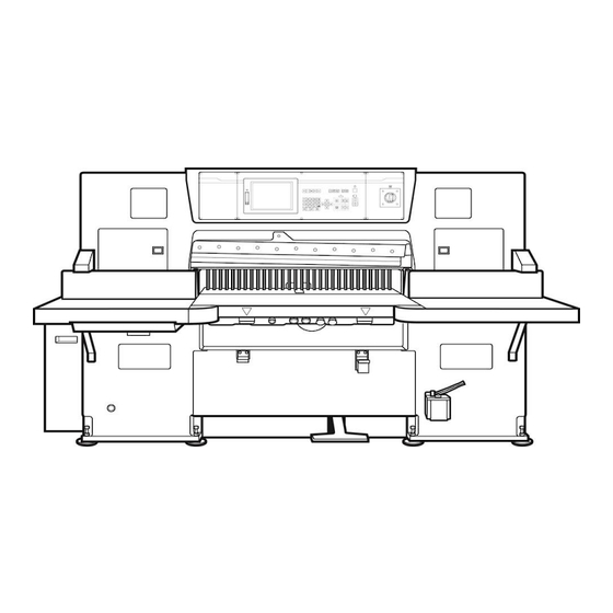
SC
Series Paper Cutter
Operation
manual
『 Applied operation ・ Maintenance 』
Ver.SCZ2001 (EN)
CAUTION
Carefully read this operation manual and be familiar with the description before
satrting operation, inspection or maintenance of the product.
The operator or administrator of this product may not have the product operated
by a person who is not familiar with the description about the product.
Advertisement
Chapters
Table of Contents

Related Manuals for Itotec SC Series


Summary of Contents for Itotec SC Series
- Page 1 SC Series Paper Cutter Operation manual 『 Applied operation ・ Maintenance 』 Ver.SCZ2001 (EN) CAUTION Carefully read this operation manual and be familiar with the description before satrting operation, inspection or maintenance of the product. The operator or administrator of this product may not have the product operated by a person who is not familiar with the description about the product.
-
Page 2: Table Of Contents
Table of Contents Index Important Safety Information How to change the knife Need customer protection ” Redidual How to remove the knife 1-4 risk map and list " How to remove the knife (Lifter) 1-3 Operation How to install the knife 1-4 How to divide the course How to install the knife (Lifter) 1-3... -
Page 3: Important Safety Information
Important safety infomation Need customer protection 「Redidual risk map and list」 Please refer to the separate volume 「 Risk assessment 」 about the following items. Need customer protection " Redidual risk map " Need customer protection " Redidual risk list "... -
Page 4: Operation
Operation How to divide the course 4 5 2 7 3 ○ You can divide the course into up to 9. ○ Even when divided, you can delete or insert a page. You can memorize multiple different tasks in one course. ○... -
Page 5: How To Use Course Jump Function
Operation How to use course jump function 5 5 3 4 7 If the work is not enough on page 50, jump to another course and page connect. ◆ Select the memory mode. While there is no need to continue the de- stination of jump, it is understandable and Store data as usual helpful to edit that the jump destination is... -
Page 6: How To Copy A Course
Operation How to copy a course 4 5 2 3 5 Copy a course. You can move or copy to another course by paste. Select the merory mode. Copy confirmation Press 【 Data confirmation 】 . Press sub mode menu 【 Others 】 . Displayed job name, memo, course number and data up to 7 pages. -
Page 7: How To Paste The Course
Operation How to paste the course 2 2 3 6 5 Copied data can be moved to another course through course pasting or it can be duplicated. ◆ Paeting can be made even if the result Select the memory mode. of pasting overflows 50 pages while the Call up the destination course of pating. -
Page 8: How To Display The Course List
Operation How to display the course list 4 5 4 2 3 Select the memory or the automatic mode. In the memory mode, press sub mode menu 【 Edit 】 , In the automatic mode, press sub mode menu 【 Main 】 . Press 【... -
Page 9: How To Copy Or Move The Course
Operation How to copy or move the course 5 10 8 7 9 Enter the destination course of copying, Select the memory or the automatic mode. using number keys. Press sub mode menu 【 Edit 】 in the memory mode, press sub mode menu Press 【... -
Page 10: How To Store Automatic Equal Division Memory 1
Operation How to store automatic equal division memory 1 2 2 3 3 4 5 Configure the automatic equal division function. Enter the ocrall length and the number of divisions of the item. Repeat size data is automatically calculated and stored. Select the memory mode. - Page 11 Operation How to store automatic equal division memory 2 3 2 4 1 5 6 3 Configure the modification / addition function for automatic eauql division . Attaching push-out Reducing the number of repeat size ( N ) by 1 Press 【...
-
Page 12: Cancel During The Excution
Operation How to cancel during the excution 2 1 Canceled because pressed the start-key. 1 The remaining times remaind displayed even if moves the cursor to outside the pge of repeat size. Cancel remaining times during the excution. Canceling is the following case. ① Change the course. -
Page 13: How To Use The Break Function Of Repeat Size
Operation How to use the break function of repeat size 2 2 ◆ ◆ How to enter data including blank A break can be inserted in continuous line. repeat size data. If the frequency is attributed to continu- The cursor does not move beyond the ous repeat size data, a blank line can be line. -
Page 14: How To Use Repetition Of Designated Range
Operation How to use repetition of designated range 2 3 3 7 3 6 A range is repeated by the enterednumber of repeat size. Select the memory mode. When paper cutting is executed in the automatic mode, a line is displayed in the Enter the first page nuimber of the repetition range at the timing of start of repeated range, followed by the decimal... -
Page 15: How To Use The Simulation Function
Operation How to use the simulation function 4 5 2 3 5 6 You can check the movement of the backgauge before cutting . Select the automatic mode. Press sub mode menu 【 Others 】 . Press 【 Simulation 】 . It warks one step each time you press "Start"-key. -
Page 16: How To Use Clamping Function To Expelair
Operation How to use clamping function to expel air 3 5 2 4 4 4 To expel air out of stacked paper, lower merely the clamp. Select the memory mode. Press sub mode menu 【 Set 】 . Enter the clamping size, using the ten-key pad. Press 【... -
Page 17: How To Use Clamping Repeat Size Function To Expelair
Operation How to use clamping repeat size function to expel air 2 4 4 3 5 6 6 Position the backgauge with the repeat size function and lower clamp only to clamp. Select the memory mode. Press sub mode memu 【 Set 】 . Enter the repeat size for clamping, using the ten-key pad. -
Page 18: How To Check The Data Monitor
Operation How to check the data monitor 1 2 4 6 3 In the manual mode In the automatic mode Press sub mode menu 【 Meinte 】 . Press sub mode menu 【 Others 】 . Press 【 Data monitor 】 . Press 【... -
Page 19: How To Check The Pedal Pressure
Operation How to check the pedal pressure 2 3 3 4 Select the manual mode. Press sub mode menu 【 maintenance 】 . Press 【 Adjust pedal pressure 】 . Displated current state. Press 【 Exit 】 . -
Page 20: Display Switching Cutting/ Knife Change Counter
Operation Display switching cutting / knife change counter 1 3 4 5 2 5 1 7 6 ◆ In all mode. When displaying the knife counter When displaying the cutting counter Press the counter on the lower left of Press the counter on the lower left of the screen. -
Page 21: Correction Of Error Between Actual Size
Operation Correction of error between actual size and displayed size 1 4 3 3 2 6 5 8 8 3 7 2 8 Correct print deviation. Use correction function Set correction on the page. Select the manual mode. Select the memory mode. Press sub mode menu 【... - Page 22 Operation Correction of error between actual size and displayed size 2 1 1 2 7 8 2 5 8 6 9 4 3 Threr are 3 method as following. 1. Input the correction value directly. 2. Move the backgauge to cutting positon and set the difference with data as correction value. 3....
- Page 23 Operation Correction of error between actual size and displayed size 3 1 1 5 3. Automatically set the correction by aligning the mark and cutting. ◆ Swlest the mamory mode or automatic Offset exceeding the permissible offset mode. range may not be entered. ◆...
- Page 24 Operation Function of size agreement detection setiing 1 1 1 2 3 Cutting is prohibited with a setting if the stored data does not agree with the bacjgauge size. The size agreement detection function includes the following. 1. Cutting is always possible. ( Initia setting ) ...
-
Page 25: Function Of Size Agreement Detection Setting 2
操作のしかた Function of size agreement detection setting 2 8 1 1 9 2 4 3 10 Set a cutting allowance range. Cutting In case of size disagreed. Select the memory mode or Automatic Select the memory mode or Automatic mode . mode . -
Page 26: How To Adjust The Backgauge Accelaration
Operation How to adjust the backgauge accelaration 1 4 2 5 3 6 Select the manual mode. Press sub mode menu 【 Set 】 . Press Option-key. Press 【 Set backgauge accelaration 】 . Adjust the accelaration or decelaration using 【 ▲ 】 【 ▼ 】 . Standard setting :... -
Page 27: How To Set The Backgauge Speed In The Automatic Mode
Operation How to set the backgauge speed in the automatic mode 1 4 2 3 5 6 ◆ Switch the speed of advance, retract and push out in the automatic mode. ◆ It does not affect driving by advance or retract button. Select the manual mode. -
Page 28: How To Set The Softwaew Limit (Advance And Retraction Limit)
Operation How to set the software limit (advance and retraction limit) 1 4 9 2 5 6 7 10 3 8 ◆ The operating range of the backgauge is controlled with software. ◆ This function is invalid after the power is turned on until zero point search is finished. -
Page 29: How To Use The Pulse Handle
Operation How to use the pulse handle 2 3 13 14 4 15 16 17 Initial setting Function setting Select the manual mode. Option set in the procedure on the left. Press sub mode menu 【 Mainte 】 . Selwct the manual mode. Press Option-key. -
Page 30: How To Set The Input Range Of The Memory Size
Operation How to set the input range of the memory size 1 4 2 5 6 3 7 7 ◆ Set the size range to be stored. ◆ The message " Out of range" is will be displyaed when a number exceeding the ... -
Page 31: How To Use The Edit History
Operation How to use the edit history 1 2 4 5 3 6 Data confirmation and recovery Use to copy Select the memory mode. After deleting a course, press 【 Data recovery 】 in the 【 Edit record 】 of the Press sub mode menu 【... -
Page 32: How To Look At The Function Selection List
Operation How to look at the function selection list 1 2 3 4 5 ◆ 【 Select unit unused course 】 Select the manual mode. Slect the unit applied to unused course. Press sub mode menu 【 Set 】 . ◆... -
Page 33: How To Set The Cutting Function
Operation How to set the cutting function 1 2 3 4 5 ◆ 【 Clamp pressure at cutting startup 】 Select the manual mode. Set the Pressur of the clamp reaching Press 【 Set 】 . the workpiece. Press 【 Cutting functio 】 . ◆... -
Page 34: How To Set The Option Function
Operation How to set the option function 1 5 8 4 2 7 3 8 The following can be set Select the manual mode. ○ Mem card Press 【 Mainte 】 . ○ Pulse handle ○ Robo-trim Press Option-key. ○ Robo-Swivel ○ Rear paper feed Press 【... -
Page 35: How To Look At The Alarm History
Operation How to look at the alarm history Select the manual mode. Press sub mode menu 【 Alarm 】 . The alarm history is displayed. Press the history screen. The cursor moves to the latest alarm. Press 【 ▲ 】 or 【 ▼ 】 to move the cursor. To edit press 【... -
Page 36: How To Protect The Data
Operation How to protect the data 2 3 3 4 3 Select the memory mode. Press 【 Others 】 . Press 【 Protect data 】 . Key mark is locked A triangular protection mark is displayed To remove protection, press once more 【 Protect data 】 . -
Page 37: How To Change The Knife
How to change the knife How to remove the knife 1 CAUTION Remove stacked paper or the like from the surface plate. Otherwise stacked paper will push out the knife holder or the like during erro- neous backgauge advance in knife change work. Leave knife change to those who have undergone special training course and observe instruction given in the instruction manual. -
Page 38: Slowly Release The Clamp Pedal
How to change the knife How to remove the knife 2 Step on the clamp pedal to lower the clamp. CAUTION When stepping on the clamp pedal, do not reach beneath the operating range of the clamp. Otherwise injyuries will be caused. While stepping on the pedal, install the clamp support bolt at two places. -
Page 39: How To Remove The Knife 1-4
How to change the knife How to remove the knife 3 While holding the knife holder securely, slowly step on the clamp pedal to lower the clamp. Cjeck if the knife handle enters the notch of the knife holder and the upper end of the knife becomes lower than the knife carrier. - Page 40 How to change the knife How to remove the knife 4 While holding the knife handle, fall the the knife on the surface plate CAUTION When placing the knife on the surface plate, do not allow the cutting edge protruding from the surface plate.
- Page 41 How to change the knife How to remove the knife (Knife lifter) 1 CAUTION Remove stacked paper or the like from the surface plate. Otherwise stacked paper will push out the knife holder or the like during erroneous backgauge advance in knife change work, possibly resulting in a broken knife and/or injuries of the operaror.
-
Page 42: While Holding The Knife Handle, Pull The Knife Towaed You
How to change the knife How to remove the knife (Knife lifter) 2 Stop the main motor. Remove the knife bolt. To remove the leftmost bolt, open the knife height adjustment window. Temporarily place the knife holder on the surface plate so that the right end of the knife is aligned with the right end of the holder cover. -
Page 43: Otherwise Injuries Will Be Caused
How to change the knife How to remove the knife (Knife lifter) 3 While holing the handles, fall the knife on the leveling block. CAUTION When placing the knife on the surface plate Do not allow the cutting edge protruding from the surface plate. -
Page 44: How To Install The Knife 1-4
How to change the knife How to install the knife 1 CAUTION Remove stacked paper or the like from the surface plate. Otherwise stacked paper will push out the knife holder or the like during erro- neous backgauge advance in knife change work. Leave knife change to those who have undergone special training course and observe instruction given in the instruction manual. - Page 45 How to change the knife How to install the knife 2 Install the knife holder and tighten the knife handle. CAUTION When removing or installing the holder or handle from/to the knife, be careful of the cutting edge of the knife, Otherwise injuries will be caused with the cutting edge.
- Page 46 How to change the knife How to install the knife 3 When holding the knife handle to make the knife into light contact with the clamp, slowly rerease the clamp pedal to raise the clamp. After the knife rises a little, slightly loosen the knife handle and, while leaving the knife holder on the surface plate, raise the knife to the top.
- Page 47 How to change the knife How to install the knife 4 Remove the knife support bolt from the clamp. CAUTION Never reach between the knife support bolt and surface plate. Otherwise entanglement will be caused between the knife support bolt and surface plate Return the knife support bolt to the predeter- mined opsition.
- Page 48 How to change the knife How to install the knife (Knife lifter) 1 CAUTION Remove stacked paper or the like from the surface plate. Otherwise stacked paper will push out the knife holder or the like during erro- neous backgauge advance in knife change work. Leave knife change to those who have undergone special training course and observe instruction given in the instruction manual.
- Page 49 How to change the knife How to install the knife (Knife lifter) 2 Install the knife holders, with the taller one on the left and shorterone on the right, and tighten the knife handoles. While holding the knife handles, eract the knife on the leveling block.
- Page 50 How to change the knife How to install the knife (Knife lifter) 3 Fix the knife to the knife carrier with bolts. Tighten bolts in order, starting at the center then outward, so that no warp is caused in the knife. To fix the leftmost bolt, open the knifeheight ajustment window.
-
Page 51: How To Adjust The Knife Height 1-2
How to change the knife How to adjust the knife height 1 3 Stop the main motor. The knife lowers. Check that the cutiing edge slightly makes contact with parer Clutch operation becomes valid after 150 seconds. and that then it starts to rise. Raise the knife to the top. - Page 52 How to change the knife How to adjust the knife height 2 Turn the clutch key counterclockwise to turn the clutch off. Close the door power electric box 1. Remove the wrench and install the worm shaft. CAUTION Be sure to remove the wrench. Otherwise the turning wrench will cause injurues.
-
Page 53: How To Make Fine Adjustment Of The Knife Height
How to change the knife How to make fine adjustment of the knife height After adjusrment is finished on the left Remove from the knife height adjusting and right sides, turn the fixing pin 90 window. degrees back to the original position. Pull the fixing pin and turn it 90 degrees. -
Page 54: How To Change The Cutting Stick
How to change the knife How to change the cutting stick Two grooves for each of the four faces of the cutting stick, total eight grooves, can be used, Stop the main motor. While inserting a screwdriver at the left end, make the cutting stick float a little to remove. Usea file or the like to remove projections ( traces of knife edge ) from the removed cuting stick. -
Page 55: How To Use Two-Stage Knife Installation Holes
How to change the knife How to use two-stage knife installation holes the knife is provided with upper and lower installation holes. At first, use the holes in the lower row. If the wear exceeds 20mm after repetitive grinding, use instaration holes in the upper row. -
Page 56: Install/Remove The False Clamp
Install/remove the false clamp How to remove the false clamp CAUTION Be sure to stop the main motor when removing or installing the false clamp. If anyone starts the clamp while another person works at the rear of the machine, injuries will be caused. - Page 57 Install/remove the false clamp How to Insatall the false clamp CAUTION Be sure to stop the main motor when removing or installing the false clamp. If anyone starts the clamp while another person works at the rear of the machine, injuries will be caused.
- Page 58 Install/remove the false clamp How to remove the false clamp (Front installation/removal) 8 1 8 1 1 9 9 6 9 12 5 11 Front installation/removal setting must be validated with an optinal function setting. Place a cushion such as abook at the Press 【...
-
Page 59: How To Install The False Clamp
Insatall/remove the false clamp How to install the false clamp (Front installation/removal) 2 4 1 1 1 3 5 5 Place a cushion such as a book at the bottom, left and right of the clamp. Keep height identical. Place the false clamp on the cushion. Align the front end of the false clamp with the cut line. -
Page 60: Maintenance
Maintenance Alarm and remedy 1 Message Remedy The protective device ( Thermal relay ) ① Operate the clutch key and manu- of the main motor is activated. ally reverse to mpve the knife to the top. ② Remove the product. ③ Determine the cause and remove it. - Page 61 Maintenance Alarm and remedy 2 Message Remedy Cutting is interrupted due to a broken ① Inspect the safety bolt and support safety bolt or loose knifesupport bolt. bolt. CAUTION If this alarm is caused during knife operation , the cutting edge of the knife may be stopped at a position lower than the bottom face of the clamp.
-
Page 62: Trouble During Operation
Maintenance Trouble during operation The power is not turned on. Remedy The touch panel shows nothing when the ① Check if the switch in the distribu- power switch is turned clockwise. tion panel or the like is turned "ON". If it is, contact the director of ... -
Page 63: How To Reset The Thermal Relay Or Pressure Alarm
Maintenance リセットボタン(黒) How to reset the thermal relay or pressure alarm Resetting the thermal relay ① Determine the cause of overload and remove it. Case ① An excessive load is detected. ② The thrmal relay is broken ② The thermal reray is activated thermally. ... -
Page 64: How To Replace The Fuse
Maintenance How to replace the fuse Turn the power switch off. Open the door of the electric box 1 or electric box 2. Reolace the appplicable fuse. The spare fuse is located in electric box 2. Check if the size ia the same and the ampere marked at the end of the fuse is identical. CAUTION Do not use the fuse unless the rating is identical. -
Page 65: How To Use The Clutch-Key
Maintenance How to use the clutch - key Application ① It is turned off during regular operation. ② Turn the key on and turn the worm shaft with a wrench to manually move the knife up or down. ③ Turn the key on/off to adjust the clutch. The clutch does not function in the following states even if the clutch key is operated. -
Page 66: How To Turn Manually
Maintenance How to turn manually The knife mechanism is manually operated. Stop the main motor. Leave the power switch turned on. Remove the cover from the worm shaft at the right side face of the main body and check the position where the wrench is installed. shaft Turn the clutch key in the electric box 1 on. -
Page 67: Safety Bolts
The machine with a broken safety bolt is stopped in an extremely unstable and dangerous state. Replacement accompanies much danger and needs professional knowledge. ITOTEC's trained engineer will conduct replacemant. オン オフ... -
Page 68: How To Replace The Safety Bolts 1
Msaintenance How to replace the safety bolts 1 Stop the main motor. Leave the power switch turned on. CAUTION The flywheel, pump pulley , V-belt and main motor pulley keep rotating due to inertia for about 150 seconds after the main motor is stopped. Check for stoppage befor continuing to work. - Page 69 Maintenance How to replace the safrty bolts 2 Remove the wrench and install the cover to the worm shaft. CAUTION Do not leave tools such as the wrench, which are used for manual rotation , installed. Otherwise the tool will jump out the shaft ,causing injuries. Insert the safety bolt from the bottom ( of rod 2 ), and install the washer and nut from the top.
-
Page 70: How To Replace The Cut-Line Bulb
Maintenance How to replace the cut-line bulb 3 4 Turn the power off. Remove the cover from the top of the main body. CAUTION When riding on the surface plate, use non-slip shoes. Otherwise you will fall or drop, suffering from injuries. Turn the lamp bulb counterclockwise and pull downward to remove. -
Page 71: How To Replace The Battery For Data Storage
Maintenance How to replace the battery for date storage The battery for backing up data is built in the internal side face of the comuter box. If the battery voltage is low, an alarm message is displayed on the touch panel display. 『... -
Page 72: Check The Clutch
Maintenance Check the clutch Fixing key for adjusting Clutch magnet Rotor Adjust nut on the start side Lining Amature Adjust nut on stope side The clutch lining becomes worn as operation continues. As the lining is worn, the gap between amature and clutch magnet produced during clutch suction becomes smaller while the gap during release becomes larger. -
Page 73: How To Adjust The Clutch 1
Maintenance How to adjust the clutch 1 Fixing key for adjusting Clutch magnet Rotor Adjusting nut on start side Lining amayure Adjusting nut on stop side Stop the main motor. Leave the power switch turned on. CAUTION The flywheel, pump pully, V-belt and main motor pully keep rotating due to inertia for about 150 seconds after the main motor is stopped. - Page 74 Maintenance How to adjust the clutch 2 Fixing key for adjusting Clitch magnet Rotor Adjusting nut on start side Lining Amature Adjusting nut on stop side Adjust the clutch-off gap. ① Remove the key ( at 1 place ) fixing the adjusting nut on stop side. ② Loosen the set screw ( at 1 place).
-
Page 75: How To Check And Replace The V-Belt
maintenance How to check and replace the V-belt 4 Adjusting bolt The V-belt becomes elongated or deteriorated as operation continues. Adjust or replace if fault is found in inspection. If deterioration in the cutting torque is felt, inspection is necessary. ◆ Inspection of V-belt tension. -
Page 76: Left/Ribht Adjustment Of The Backgauge
maintenance Left/right adjustment of the backgauge Fixing bolt Adusting screw Adusting screw If the left side If the right side (left-side) (right-side) protrudes protrudes Turn the fixing bolt counterclockwise to loosen it. Loosen the lock nut of the left/right adjusting screw on the left side, and turn it counterclockwise by the error to loosen it. -
Page 77: Vertical Adjustment Of The Backgauge 1
Maintenance Vertical adjustment of the backgauge 1 5 3 4 1 2 5 Loosen the fixing bolt. Turn the vertical adjusting screw counterclockwise by the amount of the error. Tighten the fixing bolt. Using the backgauge comb adjusting screw, adjust the gap between the front end of the backgauge comb and surface plate. - Page 78 Maintenance Vertical adjustment of the backgauge 2 5 1 Turn the backgauge comb adjusting screw clockwise to raise. Loosen the fixing bolt. Turn the vertical adjustment screw clockwise by the amount of the error. Tighten the fixing bolt. Using the backgaugecomb adjusting screw, adjust the gap between the front end of the backgauge comb and surface plate.
-
Page 79: How To Set Periodic Inspesction Timing
Maintenance How to set periodic inspection timing Select the manual mode. Press sub mode menu 【 Mainte 】 . Press 【 Periodic inspection timing 】 . Set the year, month, day using 【 ▲ 】 or 【 ▼ 】 . Press 【... -
Page 80: How To Set Oil Change Timing
Maintenance How to set oil change timing Select the manual mode. Press sub mode menu 【 Mainte 】 . Press 【 Oil change timing 】 . Set the year, month, day using 【 ▲ 】 or 【 ▼ 】 . Press 【... -
Page 81: Replacement Of Hydraulic Oil
Maintenance Replacement of hydraulic oil 5 7 CAUTION When conducting inspection, maintenance or repairs, turn the curcuit breaker off, post a " work under way " sign, post supporting workers and take other measures so that another person will not turn the power on or start operation. Otherwise injuries will be caused. -
Page 82: Replacement Of Gear Oil
Maintenance Replacement of gear oil Remove the oil cap. Prepare an empty can, Remove the blind plug and drain old oil. Close the blind plug. Supply gear oil up to the middle in the oil gauge. Install oil cap. Recommend replacement every 2000 hours. Please order us for oil change. -
Page 83: Oil Table
Maintenance Oil table Oil table Hydraulic oil Gear oil Grease Machine oil Daphne hydraulic Daphne Super Gear Daphne Super Multi Daphne Eponex Grease Idemitsu Fluid 32 Oil 320 No.2(No.3) Oil 68 Cosmo New Cosmo Grease Cosmo Oil Cosmo hidro AW32 cosmo Gear SE320 Dynamax No.2(No.3) Dynaway 68... -
Page 84: Lubrication And Grease Up
Maintenance Lubrication and grease up Grease once a year Grease once a month Machine oil once a week Varies according to the model. Capacity 0.16 lit. once a day Central lubrication in some cases. Clamp chain Remove the cover and apply grease with a brush Take care of the oil amount. -
Page 85: Cleaning 1
Maintenance Cleaning 1 1 4 5 3 3 6 7 CAUTION When conducting inspection, maintenance or repairs, turn the power off, post " work under way ", post supporting workers and take other measures so that another person will not turn the power on or start operation. Stop the main motor. - Page 86 Maintenance Cleaning 2 6 7 CAUTION When conducting inspection, maintenance or repairs, turn the power off, post " work under way ", post supporting workers and take other measures so that another person will not turn the power on or start operation. Wope off oil accumulated in the oil pan.
-
Page 87: Discarding
Maintenance Discarding Dispose of old parts after replacement or consumable parts while taking enxironmental effects into consideration. When disopsing of the cutting stick, discharge appropriately while taking enxironmental effects into consideration. When disposing of the knife, requeat a contractor so that disposal is safe with a worn out cutting edge or the like. - Page 88 Edit 2019.08 SCZ2001 (EN) http://www.itotec.co.j E-mail info@itotec.co.jp ITOTEC.CO.,LTD Head Office Funada No.10, Inuyama, Aich-pref, 484-0912, JAPAN. Phone : +81-568-67-5311 : +81-568-68-0495...
Need help?
Do you have a question about the SC Series and is the answer not in the manual?
Questions and answers