Table of Contents
Advertisement
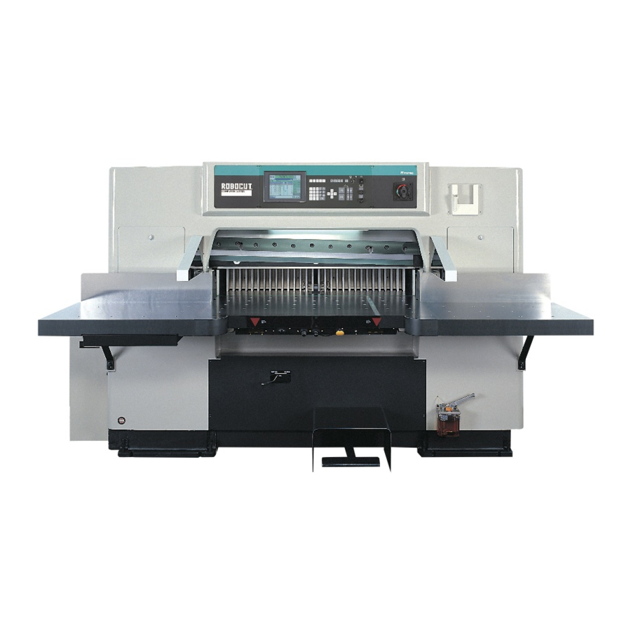
PAPER GUILLOTINE
Type No.
INSTRUCTION MANUAL
Read this instruction manual carefully and understand the contents thoroughly before
starting operation, inspection and maintenance or servicing of this product.
The operator and supervisor for this product must not have any person who does not
understand the contents of this product operate this machine.
Advertisement
Table of Contents

Related Manuals for Itotec Robocut RC-100DX


Summary of Contents for Itotec Robocut RC-100DX
- Page 1 PAPER GUILLOTINE Type No. INSTRUCTION MANUAL Read this instruction manual carefully and understand the contents thoroughly before starting operation, inspection and maintenance or servicing of this product. The operator and supervisor for this product must not have any person who does not understand the contents of this product operate this machine.
-
Page 2: Table Of Contents
Table of Contents Foreword ····················································································· Introduction Safety Precautions ······································································ Warning Label ············································································· Main Body Front Panel ································································ Parts Identification & Main Body Rear Panel ································································ Function Operation Panel ·········································································· Operation Panel Right Side ························································· Knife Button Panel ······································································· Backgauge Right & Left Adjustment ··········································· Adjustment Method Backgauge Upper &... - Page 3 Table of Contents Memroy Method (Memory Method by Ten-key) ·························· Memory & Memory Method (Memory Method by Backgauge) ····················· Setting Method Memory Method (Memory Method by Cutting) ··························· Push-out Method ········································································· Stacking position Method ···························································· How to perform soft clamp setting ··············································· How to set the clamp pressure ····················································...
- Page 4 Introduction Foreword This manual is a guide book for using this product safely. Before using this product, be sure to read this manual and thoroughly understand the operation, checkup or inspection and maintenance or servicing. Operation or the like that is different from the description given in this manual, if performed, may lead to serious accidents resulting in death or injury.
- Page 5 Introduction Safety Precautions Classification of Warning Indication To understand this instruction manual and product warning labels much better, the warning indication is classified properly as follows. Understand these contents and observe the respective instructions. This warning is used in the safety precautions and warning labels at the sections in the potential hazard state that may cause death or serious injury WARNING if not avoided.
- Page 6 Warning Label S i n c e y o u m a y CAUTION The hazardous places in this product are r e c e i v e e l e c t r i c indicated, using 6 types of warning shocks, absolutely indicator label.
- Page 7 Introduction Warning Label S i n c e t h e r e i s a Since the knife is WARNING CAUTION danger of burns due to movable, never hold a high temperature, out your hand to the a b s o l u t e l y a v o i d movable part during touching.
- Page 8 Parts Identification and Functions Main Body Front Panel Operation panel 1 Front plate This front plate is used when the paper is arranged properly. Safety beam guard If the optical axis using LED (light-emitting diode) Central lubrication pump is interrupted, the knife comes to an instant halt. Works once before start.
- Page 9 Parts Identification and Functions Rear View of Main Body Blower motor Electric box 1 Clamp presser Central lubrication pump Presses paper when cutting it. Operated once before starting. Gear box Backgauge Positions paper accurately. Power box Oil tank Electric box 2 Main motor Side guide Used to arrange paper.
- Page 10 Operation Panel × ÷ = BACKGAUGE COPY CORS COURSE PAGE PAGE PAGE DATA STOR 11 12 13 14 Mode key Power lamp Stores the data in memory. Allows all manual operations. Display panel Allows automatic positioning. Displays the backgauge size, course, page and data Allows automatic operation.
- Page 11 Parts Identification and Functions UNIT SPEED INCH FRONT BACK START MOTOR START STOP FRONT BACK STOP CLMP Ten-key Function keys Inputs the data, course and page. Lets out air. Allows push-out. Allows stacking position setting. CLMP Allows air bleeding setting. Cancels the data.
- Page 12 Operation Panel 2 Pressure 2000 3000 T.D.C 1000 4000 PRESSURE KNIFE LIFTER HIGH UP DOWN Knife lifter switch (Option) Pressure lamp The lamp lights up if the hydraulic circuit monitor function for monitoring the state of the hydraulic circuit during operation of the knife button detects Clamp pressure adjusting knob an error.
- Page 13 Parts Identification and Functions Cutting Buttons Panel Knife support bolt Cutting button Lowers the knife with the right and left buttons Used for knife change. depressed at the same time. By pressing either * Not provided for models with a knife lifter. button, the air is stopped.
-
Page 14: Backgauge Right & Left Adjustment 1
Adjustment Method Backgauge Right & Left Adjustment 1 When the backgauge left is protruding as viewed from the main body front panel Turn the fixing bolt clockwise to fix CAUTION Be sure to use the supplied spanner. Check the adjusted results. Do not apply excessive force to the spanner;... - Page 15 Adjustment Method Backgauge Right & Left Adjustment 2 When the backgauge right is protruding forward as viewed from the main body front panel Turn the fixing bolt clockwise to fix CAUTION Be sure to use the supplied spanner. Check the adjusted results. Do not apply excessive force to the spanner;...
-
Page 16: Backgauge Upper & Lower Adjustment 1
Backgauge Upper & Lower Adjustment 1 When the backgauge is leaning forward Adjust the clearance between the CAUTION aft comb tip and table with the aft comb upper & lower adjusting pin. Be sure to use the supplied spanner. Do not apply excessive force to the spanner;... - Page 17 Adjustment Method Backgauge Upper & Lower Adjustment 2 When the backgauge is leaning backward Turn the fixing bolt clockwise to CAUTION tighten it. Be sure to use the supplied spanner. Do not apply excessive force to the spanner; for example, do not rest your weight thereon.
-
Page 18: Clamp Pressure Adjustment
Clamp Pressure Adjustment Turn the power switch "ON". Work the clamp pedal to ensure that the clamp lowers onto the table side. Start hydraulic motor operation. Select the pressure with the clamp pressure adjusting knob and clamp pressure level selector switch. Impact paper Middle quality paper High quality paper... -
Page 19: Confirmation Of Knife Height
Adjustment Method Confirmation of knife height Be sure to check after the knife is changed. Turn the power on. If the knife lowers too much or if it does not make contact with the paper or if the knife height varies between the left and CAUTION right sides, adjust the height of the knife (page... - Page 20 Fine adjustment of height of knife Remove the lid of the knife height adjusting window. Pull the fixing pin and turn it 90 degrees. Using the adjusting handle, adjust the height. Turn the adjusting handle toward the depth to raise the knife, or turn it toward you to lower the knife.
-
Page 21: To Determine Knife Angle
Adjustment Method To Determine Knife Angle The knife angle significantly affects the cutting quality or sharpness. Changing the angle according to paper quality produces an effect. The standard angle is 22 degrees. For hard paper, however, approx. 25 degrees will be acceptable, and for soft paper, the angle will favorably be approx. 19 to 20 degrees. Reducing the angle to 19 degrees or smaller causes the edge to be nicked. -
Page 22: To Replace Cutting Stick
To Replace Cutting stick Stop the main motor. CAUTION When the knife cuts too deep into the cutting stick and the paper is broken Insert a screwdriver from the left without cutting only on the paper lower end, and take out the cutting stick part, replace the cutting stick with a new while keeping it afloat little by little. -
Page 23: How To Change The Safety Bolt
Adjustment Method How to change the safety bolt If a hard matter or foreign matter is cut or a dull knife is used to cut, the safety bolt will be broken to stop the knife in an emergency. Stop the main motor. Turn off the clutch key. -
Page 24: How To Install The Back Plate
How to install the back plate Turn the power off. CAUTION When the back plate is installed, the backgauge protrusion distance is limited Align the dowel pins of the back to 85 mm. plate with the dowel pin holes of the clamp. -
Page 25: How To Read Information Display
Operation Method How to read information display To reset the tripping thermal relay, When the thermal relay trips or the press the thermal button in electric safety bolt is broken, error display box 2. appears. The nature of the error is displayed, using a number. -
Page 26: Introduction
Operation Method CAUTION Ensure that foreign matter or the like is not present on the table. Ensure that no foreign matter is found around the machine, especially at the foot in the working position and near the pedal. Also, take special care so that the cutting material near or around the cutting machine does not crumble or fall down. -
Page 27: To Operate Cutting Button
Operation Method To Operate Cutting button Press the right and left cutting buttons at the same time. CAUTION Continue to press the cutting buttons until the knife reaches the cutting stick. If it is released midway, the knife will stop in that position. -
Page 28: To Operate Backgauge
To Operate Backgauge When giving instructions with the size from the knife edge This is effective in all modes. Input the objective position data with Ten-key. Press the START key. The backgauge travels to the objective position, coming to a halt. When giving instructions with the backgauge present position as reference This is effective in all modes. -
Page 29: To Change Backgauge Speed
Operation Method To Change Backgauge Speed This is effective in all modes. Press the SPEED key. Each time this key is depressed, the backgauge speed can be changed to 4 steps below. The backgauge forwards at a low speed, and backwards at the normal speed. -
Page 30: To Change Unit
To Change Unit This is effective in all modes. This operation applies only to when the data is not saved in the course now on the display. Press the UNIT key. Each time this key is depressed, the unit is changed to "mm", "inch", then "mm". - Page 31 Operation Method To Correct Errors Between Exact Size and Indicated size Measure the error accurately. Press the STOR key. The numerical value displayed in step above is changed. Select the manual mode. Example Where the exact size is 0.5 mm smaller than the indicated size Press the SCH key.
-
Page 32: To Call Course
To Call Course This is effective in all modes. Input the course to be accessed with Ten-key. Press the CORS key. -
Page 33: To Call Empty Course
Operation Method To Call Empty Course Select the DS mode. Press the SCH key. The empty course is on the display. Call the youngest of the empty courses. -
Page 34: To Erase Course
To erase Course If the course may be erased after Select the DS mode. checking, press the ERA key once more. Input the course to be erased with If it is not desired to ERA the course, Ten-key. press the CL key. This erasure will be cancelled. -
Page 35: To Call Page
Operation Method To Call Page This is effective in all modes. Input the page to be accessed with Ten-key. Press the PAGE key. The page can be called even when the PAGE key is depressed without calling it with Ten-key. By pressing [PAGE +] once, the PAGE screen scrolls one page. -
Page 36: To Insert Page
To Insert Page When it is desired to insert a data into the course already stored in memory Select the DS mode. Input the data to be inserted with Ten-key. Input the page to be added with Press the STOR key. Ten-key. -
Page 37: To Delete Page
Operation Method To Delete Page Select the DS mode. Input the page to be deleted with Ten-key. Press the PAGE key. Ensure that the page and data are displayed on the display panel. Press the DEL key. The page size is deleted, and the page is carried over automatically. - Page 38 To Use Cut line optical Turn the working lamp switch "OFF". The table lighting goes out, and cutting line is shown on the paper.
-
Page 39: To Use Air Table
Operation Method To Use Air Table Set the air selector switch to the rear ----- the air normally blows out. Set this switch to the center ----------------- the air stops. Set this switch to the forward position ---- the air blows out only when the backgauge moves backward. -
Page 40: How To Show Counter Display
How to show counter display How to show counter display The procedure is effective in all modes. Press the equal key. The count is displayed at the data display while the key is held down. How to clear the counter Select the manual mode. - Page 42 Memory and Setting Method Memory Method (Memory Method by Ten-key) After completing the input, select Select the DS mode. the SA mode. Set the course. Press the START key. W h e n t h e p r e v i o u s m e m o r y remains, be sure to press the ERA key twice to ERA the size stored in memory.
- Page 43 Memory and Setting Method Memory Method (Memory Method by backgauge) Store the size in memory while moving the backgauge without lowering the knife. Upon completion up to the final Select the DS mode. stroke, select the SA mode. Set the course. Press the START key.
- Page 44 Memory Method (Memory Method by Actual Paper Cutting) Select the DS mode. Set the course. W h e n t h e p r e v i o u s m e m o r y remains, be sure to press the ERA key twice to ERA the size stored in memory.
- Page 45 Memory and Setting Method Push-out Method Select the DS mode. To cancel the push-out, select the page to be cancelled and press "0" with Ten-key, then press the P key. Input the page to be protruded with Ten-key. To check the push-out size, press the P key.
- Page 46 Stacking Position Method Before the paper is cut, the position of backgauge convenient for proper paper arrangement can be set. Upon completion of protrusion and Select the DS mode. arrangement during paper cutting operation, press the START key. (SA/FA modes) Input the stacking position size into Step to the next page: the backgauge moves.
- Page 47 Memory and Setting Method How to perform soft clamp setting Select the manual mode. Press the air release key. The pressure is displayed at the data display. You can set a number between 0 (weak) and 9 (strong), with 5 being the standard. To increase the pressure, press the + key;...
- Page 48 How to set the clamp pressure Set the clamp pressure for each course. Select the semi-automatic or If the entered data is wrong or to automatic mode. cancel it, press the cancel key. Select the desired course for To cancel pressure setting and use pressure setting.
- Page 49 Memory and Setting Method How to set the clamp timer You can set a delay in the ascent of the clamp to push the cut workpiece against the clamp and assort it easily. Press the push key. Select the semi-automatic or automatic mode.
- Page 50 Applied Operation Method Expell Air Method To let out air in the paper ream, send out the backgauge and lower the clamp only. Select the DS mode. Input the air bleeding size with Ten-key. Press the CLMP key. Press the STOR key. CAUTION When the "DS"...
- Page 51 Applied Operation Method Full-Automatic Operation Method Select the FA mode Press the "FAA" key The buzzer sounds. Press the cutting button only first to lower the knife. A c c o r d i n g t o t h e d a t a , t h e backgauge moves and the knife lowers.
- Page 52 To Copy Data The data in page can be copied to another page. Example Select the DS mode. Page 500.00 400.00 300.00 Call the empty page to be copied. 200.00 Copy Input the page you desire to start copying with Ten-key. When the size of pages 1 to 3 is copied to pages 4 to 6, make 4 pages and press "1"...
- Page 53 Applied Operation Method To Use Calculation Function This is effective in all modes. Normal calculation can be carried out, using thecalculation key. The progress and results are displayed on the datadisplay unit. When it is desired to memory the calculated results in page, press the "STOR"...
- Page 54 To Use Spare Course When it is desired to memory 30 pages or more in page in one course, up to 50 pages can be stored in memory by linking to the spare course. (The spare course consists of 10 courses, and 20 pages are available in each course.) If the size is srored in memory with 29 pages, the current course will be linked to the spare course automatically, thus making it possible to store up to 49 pages in memory.
- Page 55 Applied Operation Method To Use Hold Feed Key and Number of Repetition Key Hold Feed Key This key is used to send out the backgauge forward at the equal size. Input the size for sending out the backgauge with Ten-key and press the "H"...
- Page 56 How to change the knife How to remove the knife WARNING To remove the knife, prepare necessary tools and so on in advance and follow the correct steps carefully. Select the manual mode. Press the knife button and, after the knife has reached the bottom, release the knife button.
- Page 57 How to change the knife Release the clamp pedal slowly. The clamp rises and the knife support bolts support the cutting edge. Remove the knife installation bolts. Open the knife height adjusting window to remove the leftmost bolt. CAUTION Never lower the clamp. Otherwise the knife will fall.
- Page 58 Slowly release the clamp pedal. Hold the knife handles to pull the knife toward you. CAUTION Do not allow your hand to slip due to oil or the like. CAUTION Do not hit the left or right end against the main body when removing the knife.
- Page 59 How to change the knife How to install the knife WARNING To install the knife, prepare necessary tools and so on in advance and follow the correct steps carefully. Place the knife on the leveling block, with the cutting edge facing you. CAUTION Do not protrude the cutting edge out of the leveling block.
- Page 60 Install the two knife support bolts to the clamp. While holding the knife handles, release the clamp pedal slowly to raise the clamp. After the knife is raised a little, slightly loosen the knife handles to detach the knife holders. CAUTION Check that the knife handles enter the notches of the middle plate.
- Page 61 How to change the knife Step on the clamp pedal to lower the clamp. Remove the knife support bolts from the clamp. Return the knife support bolts to the predetermined positions. If they are not returned correctly, the knife does not lower. Move the knife change lever into the CUTTING position.
- Page 62 How to remove the knife (for models with a knife lifter) WARNING To remove the knife, prepare necessary tools and so on in advance and follow the correct steps carefully. Select the manual mode. Press the knife button until the knife reaches the bottom, then release the knife button.
- Page 63 Use the knife lifter switch to lower the knife. Install the knife handles and knife holders. Remove the hanging bolt. While holding the knife handles, pull the knife toward you. CAUTION When pulling the knife, avoid hitting the cutting edge against the main body. While holding the knife handles, fall the knife on the leveling block.
- Page 64 How to install the knife (for models equipped with a knife lifter) WARNING To install the knife, prepare necessary tools and so on in advance and follow the correct steps carefully. Stop the main motor. The knife lifter does not function if the main motor remains turned on.
- Page 65 Using the knife lifter switch, lift the knife to the top. CAUTION Take care of the hole position so that the knife does not rise excessively. If it does, a protective relay for the lifter motor functions. Fix the knife to the middle plate, using bolts.
- Page 66 Oil Changing Method Hydraulic Oil Change Detach the oil strainer and wash it Stop the main motor. in light oil. Remove the oil tank cover. Re-install the oil strainer. Apply new oil up to the mid-position Extract the oil, using the siphon type of the oil gauge as shown below.
- Page 67 Replacement of gear oil Remove the oil cap. Prepare an empty can and open the blind plug to drain old oil. Close the blind plug. Supply gear oil to the middle of the oil gauge. Install the oil cap. Follow the same procedure for the left and right.
- Page 68 Lubrication and Greasing-up Machine oil Greasing once per day once per month...
- Page 69 Oil Changing Method Oil Table Hydraulic Oil Grease MOBIL Mobil DTE 24 Mobilux No.2 SHELL ESSO Tellus Oil 32 Alvania No.2 GULF Nuto H32 Beacon No.2...
- Page 70 Repair Service & Specifications Repair Service When an abnormality occurred in the product, contact the agent where purchased. When asking us for repair, always specify the following - Failure status (Describe as minutely as possible.) - Type - Machine No. - Date of delivery - Your company name - Your address...
- Page 71 Repair Service & Specifications Specifications Main body Paper cutting width 1030 mm 40 1/2" Paper cutting depth 1000 mm 39" Clamp opening 165 mm 6 1/2" Front table length 650 mm 27 1/2" Table height 875 mm 34 1/2" Main body width 2285 mm 90"...
Need help?
Do you have a question about the Robocut RC-100DX and is the answer not in the manual?
Questions and answers