Advertisement
Quick Links
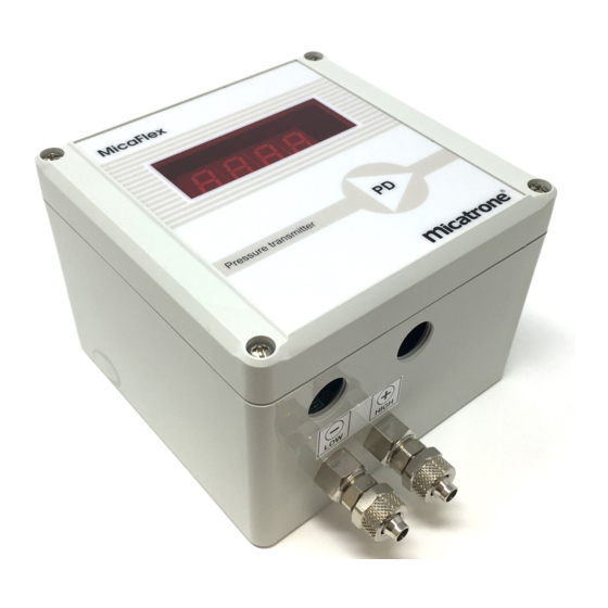
Micafl ex PD ver 4
Differential pressure transmitter with
microcontroller and digital indication
NOTE !
Read through the entire manual before you begin in-
stallation and programming.
APPLICATION
MF-PD is a pressure transmitter designed for measur-
ing of low positive, negative and differential pressure.
MOUNTING
MF-PD is designed for wall mounting but can be fi tted
with an optional frame kit, MFM-PANEL, for recessed
mounting in a wall or through a cabinet door.
MF-PD is screwed to the wall using four screws, max
ø 4mm. Location of screw holes are shown on the re-
verse of the enclosure.
PRESSURE CONNECTIONS
Pressure connection can be made with mounting kit
VR-DR or HT-plastic tube 8/6 mm.
• Connect positive pressure to [+] connection.
• Connect negative pressure to [-] connection.
NOTE! Leave unused connections open to the at-
mosphere.
For differential pressure measurement, the highest
pressure is connected to the [+] connection. If the
transmitter has a pressure range with zero-crossing
(i.e -50...50 Pa) the high pressure connection [+] is
connected to the measuring area and the low pressu-
re connection [-] is connected to the reference area.
OUTPUT SIGNAL SELECTION
Volt and mA signal have different wiring terminals.
Verify that the correct output is connected.
See instructions on our web site.
Programming keys
Miniature switch
Adjustment keys
LED
Zero-setting key
Installation- & Operation manual
ZERO ADJUSTMENT
Switch on the main supply and wait at least 60 sec.
Set the manifold valve in position calibration (if there
is no valve, loosen the pressure tubes from the MF-
PD). Remove the cover to access the Zero-setting
key on the main circuit board. Check that the minia-
ture switch no 2 is in position "OFF". Press down the
Zero-setting key, the LED starts fl ashing. Keep the
key pressed until the LED turns off. Release the key
and the zero-setting is fi nished.
SETTING OF DAMPING
MF-PD offers a possibility to set different damping
(time constant). At delivery of MF-PD, the damping is
set to 1,5 seconds damping. Setting is adjusted with
the miniature switch no 4 and 5 (the switch is situated
on the bottom left edge of the main circuit board).
HALF MEASURING RANGE
Set the miniature switch no 1 in position "OFF" for full
measuring range (100%) or in position "ON" for half
measuring range (50%).
NOTE! The accuracy is always for the full range.
ADJUSTING THE MEASURING RANGE
The measuring range can be adjusted to correct a
measuring deviation. Instruction can be found on our
website, www.micatrone.com.
FORCED OUTPUT SIGNAL
Max output signal (10 Volt and 20 mA) is obtained
when miniature switch no 3 is set to position "ON". This
function can be used to check the receiving system.
[© AB Micatrone, mi-334gb_181204] Page 1 of 4
[Doc. id: mi-334gb_181204]
MF-PD
ver 4
Advertisement

Related Manuals for Micatrone Micaflex PD ver 4


Summary of Contents for Micatrone Micaflex PD ver 4
- Page 1 Max output signal (10 Volt and 20 mA) is obtained Miniature switch when miniature switch no 3 is set to position ”ON”. This function can be used to check the receiving system. Zero-setting key [© AB Micatrone, mi-334gb_181204] Page 1 of 4...
- Page 2 After 5 minutes, with no key has been used, the pro- a negative pressure, a minus sign can illuminate in gramming is terminated automatically. the display by programming P04 to Neg. NOTE! For transmitter with zero-crossing range, P04 is NOT accessible. Page 2 of 4 [© AB Micatrone, mi-334gb_181204]...
- Page 3 The full text of Manufacturers declaration of con- formity is available on Micatrones website. CONNECTION 24 VAC / 20...32 VDC CONNECTION 24 / 115 / 230 VAC (without transformer) (with built-in transformer) [© AB Micatrone, mi-334gb_181204] Page 3 of 4...
- Page 4 485 serial connection. See separate instruction for Modbus RTU. Modbus RTU can NOT be used with Alarm module or Transformer. AB Micatrone Telephone: +46-8-470 25 00 Aldermansvagen 3 SE-171 48 SOLNA Internet: www.micatrone.com SWEDEN E-mail: info@micatrone.se Page 4 of 4 [© AB Micatrone, mi-334gb_181204]...
Need help?
Do you have a question about the Micaflex PD ver 4 and is the answer not in the manual?
Questions and answers