Table of Contents
Advertisement
Quick Links
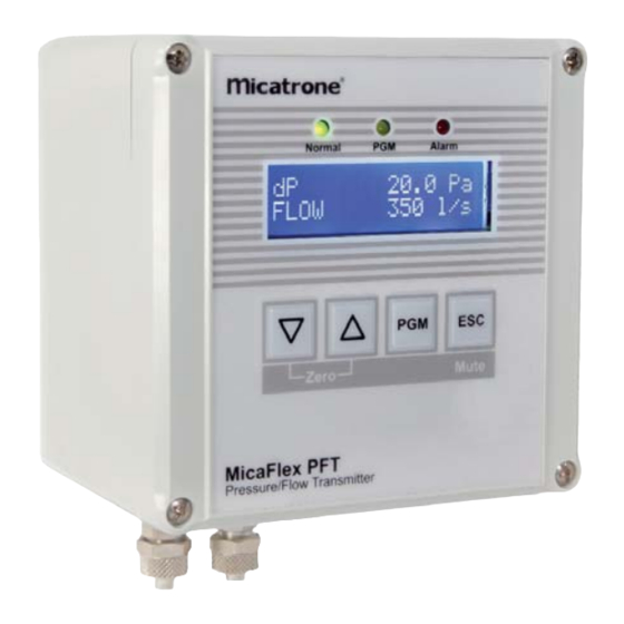
Micafl ex PFT ver 3.
Pressure- and Flow transmitter with
control output
NOTE !
Read through the entire manual before you begin
installation and programming.
APPLICATION
MF-PFT is a microprocessor controlled transmitter/
controller for measurement and control of differential
pressure or fl ow. With the four keys on the front panel
it is possible to access all functions, make settings
and scaling the output signal. The double row, 2x16
character, LCD with backlight displays functions and
values.
MOUNTING
MF-PFT is designed for wall mounting but can be
fi tted with an optional frame kit, MFM-PANEL, for
recessed mounting on wall or through a cabinet door.
MF-PFT is screwed to the wall using four screws, max
ø 4mm. Location of screw holes are shown on the
backside of the enclosure.
Unscrew the lid and use the bottom screws to
temporarily fi x the lid on the upper edge of the
enclosure during installation. See fi gure.
OUTPUT SIGNAL
MF-PFT has two analogue output signals which can be
used for pressure, fl ow or control signal. Each output
has three terminals, one for Volt DC, one for mA DC
and one common zero. The outputs allow both the Volt
and mA signals to be used simultaneously.
If the unit is fi tted with built-in automatic zero-setting
module MFM-ZP, it is connected to output 2 (Volt or
mA). It is still possible to use the free output signal on
output 2 for the selected source.
ALARM
MF-PFT has two alarms, each independent of the
other. The alarm is acoustic with beeper and visual
with LED indication for pressure or fl ow, high or low
alarm level and manual or automatic reset.
START MENU
When the transmitter is connected to supply voltage, a
start menu is displayed.
Using the arrow-keys it is possible to scroll through the
different available start menus. To have the unit always
displaying the same start menu, it can be selected and
programmed in parameter group System settings.
By pressing the ESC-key when other menus are
displayed the selected start menu is displayed.
Installation- & Operation manual
A
PROGRAMMING
Push the PGM-key until "PROGRAM-MENU" is
displayed. Release the PGM-key and the fi rst parameter
group is displayed according to the parameter list on
page 2.
Using the arrow-keys it is possible to scroll through
the different available parameter groups. Note, If code
lock is activated, see page 6, the programmed 4-digit
access code must be entered to access the menu.
1.
Internals
2.
System settings
3.
Output 1
4.
Output 2
5.
Pressure
6.
Flow
7.
Alarm 1
8.
Alarm 2
9.
PI Controller
10. AutoZero
11. Communication
When the desired parameter group is displayed, press
the PGM-key to select the group for programming. The
available parameters in the selected parameter group
is displayed on the bottom row.
Use the arrow-keys to select which parameter to
program and press the PGM-key.
[© AB Micatrone, mi-302gb_171025] Page 1 of 8
[Doc.id: mi-302gb_171025]
MF-PFT
ver 3.x
A
Advertisement
Table of Contents

Related Manuals for Micatrone MF-PFT


Summary of Contents for Micatrone MF-PFT
-
Page 1: Control Output
fi tted with an optional frame kit, MFM-PANEL, for recessed mounting on wall or through a cabinet door. MF-PFT is screwed to the wall using four screws, max ø 4mm. Location of screw holes are shown on the backside of the enclosure. - Page 2 Source If no key has been pressed during 5 minutes, the FLOW program menu is closed automatically. Limit MinRange MaxRange Delay [s] 3600 Page 2 of 8 [© AB Micatrone, mi-302gb_171025]...
- Page 3 0/4 mA. • P22 Max out, Higher limit for scaling the output MF-PFT has 2 output signals which can be set to either signal is set in pressure units, e.g. 90 Pa will result 0..10 Volt, 2..10 Volt, 0..20 mA or 4..20 mA. Both Volt at 90 Pa pressure the max output signal of 10 V and mA are simultaneously available for both outputs.
- Page 4 3276,7. Of the same reason, 500,0 cannot be adjusted to 500,00. MF-PFT has an alarm with two, each independent, • P26 Max fl ow, set the fl ow that correspond to the alarm limits. The alarm is acoustic with buzzer and pressure range on the MF-PFT.
- Page 5 REVERSE REVERSE DP/Flow Min output [%] Max output [%] MF-PFT has a PI-controller specially made for pressure and fl ow control. Setpoint The controller could be programmed as a standard PI- I-time BZ controller, but in most of the applications together with...
- Page 6 Protect 5. If the entered access code is incorrect, the text “INVALID CODE” is displayed during 2 seconds. MF-PFT can be fi tted with a built-in expansion module Restart from point 1. (Option) for network communication with a computer. 6. By pressing the ESC-key, the entering code...
- Page 7 Zero setting of pressure transmitter Calibration of MF-PFT Disconnect the pressure connections or place the MF-PFT can be re calibrated against a pressure block valve in position calibration. reference. Press repeatedly on the ESC-key until the start menu 1. Keep PGM and ESC pressed until following text is displayed.
- Page 8 Degree of protection: IP 65, ABS plastic ELECTRICAL CONNECTION: Main connection board 24 VAC/VDC Output 1 Output 2 AB Micatrone Telephone: +46-8-470 25 00 Aldermansvagen 3 Fax: +46-8-470 25 99 SE-171 48 SOLNA Internet: www.micatrone.se SWEDEN E-mail: info@micatrone.se Page 8 of 8 [© AB Micatrone, mi-302gb_171025]...
Need help?
Do you have a question about the MF-PFT and is the answer not in the manual?
Questions and answers