Table of Contents
Advertisement
Quick Links
Document Ref:
0606829a
Date:
Wednesday, November 21, 2018
This document was prepared by the staff of Valeport Limited, the Company, and is the property of the
Company, which also owns the copyright therein. All rights conferred by the law of the copyright and by virtue
of international copyright conventions are reserved to the Company. This document must not be copied,
reprinted or reproduced in any material form, either wholly or in part, and the contents of this document, and
any method or technique available therefrom, must not be disclosed to any other person whatsoever without
the prior written consent of the Company.
Valeport Limited
Tel:
St Peters Quay
e mail:
Totnes
Web:
Devon, TQ9 5EW
United Kingdom
As part of our policy of continuous development, we reserve the right to alter, without prior notice, all
specifications, designs, prices and conditions of supply for all our equipment.
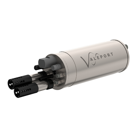
MIDAS CTD+
Operating Manual
+44 1803 869292
sales@valeport.co.uk | support@valport.co.uk
www.valeport.co.uk
Advertisement
Table of Contents

Related Manuals for Valeport MIDAS CTD+


Summary of Contents for Valeport MIDAS CTD+
- Page 1 Wednesday, November 21, 2018 This document was prepared by the staff of Valeport Limited, the Company, and is the property of the Company, which also owns the copyright therein. All rights conferred by the law of the copyright and by virtue of international copyright conventions are reserved to the Company.
-
Page 2: Table Of Contents
5.1. Optionally Fitted Sensors ............................ 23 6. Wiring Information ............................. 24 6.1. 3m Y Lead (RS232) ............................ 24 6.2. Remote Fluorometer Flylead ............................ 24 6.3. Water Sampler Motor Flylead ............................ 25 7. Warranty ............................. 26 © 2018 Valeport Ltd Page 2... -
Page 3: Introduction
1. Introduction This section of the manual describes the specification, construction, wiring diagrams and basic maintenance procedures of the Valeport MIDAS CTD+ Multi-Parameter CTD, including the optional additional sensors and water sampling system. The MIDAS CTD+ system consists of the following components: ·... -
Page 4: Specifications
20Bar absolute (approx 200m water depth) as standard, others available on request Accuracy: ± 0.1% Full scale Resolution: 0.005% Full scale Temperature Type: Fast response PRT Range: -5 to +35°C Accuracy: ± 0.01°C Resolution: 0.002°C © 2018 Valeport Ltd Page 4... -
Page 5: Optionally Fitted Sensors
However, this primary data output may be subjected to a secondary, or “User” calibration within the instrument, so that the output is converted into engineering units, for example mg/l. Details of how to perform these User calibrations are given in a separate manual. Page 5 © 2018 Valeport Ltd... -
Page 6: Mechanical Specifications
10 pin female SubConn bulkhead type with lock ring, data and power Comms Cable: Valeport 3m Y lead. 10 pin male SubConn line type to instrument, 2 x 4mm banana plugs to external power, 9 pin female D type to PC. -
Page 7: Performance Specifications
316 grade stainless steel. Dimensions: assembled size is 92cm diameter x 1.7m high Fittings: Provision for 12 x 2.5litre water bottles, 1 x Valeport MIDAS CTD+ CTD, 1 x WS Envirotech EcoLab system. Weight: 48kg (excluding instruments and bottles) 2.3.2.3. Sample Bottles... -
Page 8: Sample Lifetime Calculations
7 bytes of time stamp. Each record therefore uses 19 bytes. A single cast will take 12,000 such records and will, therefore, use 228,000 bytes. The 8Mbyte memory will therefore hold approximately 35 casts of data. © 2018 Valeport Ltd Page 8... - Page 9 75% efficient (total available charge, 10.5Ah), and that an 8 D cell Lithium pack will have a nominal capacity of 17.5Ah, and will be 95% efficient (total available charge, 16.6Ah). Note: the following examples are intended as guides only. Valeport accepts no responsibility for variation in actual performance Note: the performance of individual battery cells is not always consistent 2.5.2.1.
- Page 10 Total charge available is 10500mAh. Number of hours available is therefore 10500mAh / 6.72mA = 1562 hours. This is equivalent to approx 65 days. For Lithium cells, a similar calculation gives approx 156 days. © 2018 Valeport Ltd Page 10...
-
Page 11: Installation
For profiling work, the recommended deployment method is to suspend the instrument using the stainless steel wire strop. For fixed deployments, the user may wish to remove the steel cage, and use the grooves in the titanium instrument housing as clamping points. Page 11 © 2018 Valeport Ltd... - Page 12 For real time data output, connect the signal cable to the 10 pin SubConn connector on the instrument. All Valeport signal cables include a suspension point for strain relief, and a similar arrangement is recommended for other cable types. Connect the top end of the cable to a PC using the appropriate method as described above.
-
Page 13: Deployment Of The Water Sampler System
310mm diameter clamping rings for EcoLab (1 packed separate, 1 fixed to bottom frame) motor assembly (not illustrated) Begin by separating the top and bottom frames, by undoing the wing nuts holding them together: Page 13 © 2018 Valeport Ltd... - Page 14 Next, place the bottle mounting ring on the rods, taking care to position it the right way up. The thread on the top of the rods should fit through the holes in the ring. Then, screw the 20cm rods in place as shown, tightening as much as possible. © 2018 Valeport Ltd Page 14...
- Page 15 The instrument must be removed from this frame to allow it to fit into the water sampler frame. Remove the instrument from its frame as shown in the picture. Page 15 © 2018 Valeport Ltd...
- Page 16 The white plunger is spring loaded, and should release into the hole in the frame, locking it in place. Arm the bottles using the following procedure: Push forward the release lever, and secure in place with the rotating plate. © 2018 Valeport Ltd Page 16...
- Page 17 Release the remainder of the sample by slowly release the screw on the top of the bottle. This allows the water to drain out of the tap under atmospheric pressure. Page 17 © 2018 Valeport Ltd...
-
Page 18: Maintenance
This Chapter also covers details of the o-rings that are fitted to the instrument, and which should be checked regularly for damage and replaced if necessary. © 2018 Valeport Ltd Page 18... -
Page 19: Changing Batteries
7. Check the condition of the bore seal o-rings and apply a light coating of silicon grease. Ensure that they sit in the groove correctly, and are free from damage. Replace them if necessary. Page 19 © 2018 Valeport Ltd... -
Page 20: O-Ring Sizes
If obtaining further spare o-rings from an alternative source, be sure to obtain the correct material (signified by the last 4 digits of the o-ring code number). O-ring size: 200-158-4470 Anti-Extrusion ring size: © 2018 Valeport Ltd Page 20... -
Page 21: Replenishing Pressure Balance Fluid In Motor Housing
Remove the bleed screw, and using the syringe supplied, fill the housing with Fluorinert (approx 200ml are supplied for this purpose). When the housing is full, refit the bleed screw and tighten. Page 21 © 2018 Valeport Ltd... -
Page 22: Sensor Information
Note also that this cap contains a small sponge, which should be kept moist with reference solution during instrument storage. If a Valeport Hyperion Turbidity sensor is fitted it will be via a connector and not fitted to the bulkhead as shown above. -
Page 23: Optionally Fitted Sensors
5.1. Optionally Fitted Sensors For optionally fitted sensors please see the specific manuals: For the latest manuals please download from the following websites: Valeport Hyperion Fluorometer: www.valeport.co.uk/Support/Manuals SeaPoint Turbidity Meter: www.seapoint.com/pdf/stm_um.pdf OxyGuard D.O. Profile: www.oxyguard.dk/products/probes/do-profile-2/ Page 23 © 2018 Valeport Ltd... -
Page 24: Wiring Information
6.2. Remote Fluorometer Flylead END 1: END 2: FUNCTION 6 WAY MALE SUBCONN IMPULSE AG306 MCIL6M + LOCKING SLEEVE PWR GND SENSOR SIG (0-5v) SIG GND SENSOR PWR (10v) GAIN CTRL A GAIN CTRL B © 2018 Valeport Ltd Page 24... -
Page 25: Water Sampler Motor Flylead
6.3. Water Sampler Motor Flylead END 1: END 2: 5 WAY MALE SUBCONN MCIL5M 5 WAY FEMALE SUBCONN MCIL5F FUNCTION + LOCKING SLEEVE + LOCKING SLEEVE Motor +10V Motor 0V +5V Sensor 0V Sensor Sensor O/P Page 25 © 2018 Valeport Ltd... -
Page 26: Warranty
0606829a - MIDAS CTD+ 7. Warranty © 2018 Valeport Ltd Page 26...
Need help?
Do you have a question about the MIDAS CTD+ and is the answer not in the manual?
Questions and answers