National Instruments sbRIO-9605 Operating Instructions And Specifications
Single-board rio oem devices
Hide thumbs
Also See for sbRIO-9605:
- Operating instructions and specifications (33 pages) ,
- Operating instructions and specifications (34 pages)
Table of Contents
Advertisement
OEM OPERATING INSTRUCTIONS AND SPECIFICATIONS
NI sbRIO-9605/9606 and
NI sbRIO-9623/9626/9633/9636
Single-Board RIO OEM Devices
The NI sbRIO device must be installed inside a suitable enclosure prior to use.
Caution
Hazardous voltages may be present.
Caution
National Instruments makes no product safety, electromagnetic compatibility
(EMC), or CE marking compliance claims for NI sbRIO devices. The end-product supplier
is responsible for conformity to any and all compliance requirements.
Caution
Exercise caution when placing NI sbRIO devices inside an enclosure. Auxiliary
cooling may be necessary to keep the local ambient temperature under the maximum rating
for the NI sbRIO device. Refer to the
maximum local ambient temperature rating.
This document provides dimensions, pinouts, connectivity information,
and specifications for the National Instruments sbRIO-9605, sbRIO-9606,
sbRIO-9623, sbRIO-9626, sbRIO-9633 and sbRIO-9636. The devices are
referred to inclusively in this document as the NI sbRIO device.
The NI sbRIO device is available in different configurations. When a
feature pertains only to specific models, a list at the beginning of the section
shows which models support the feature.
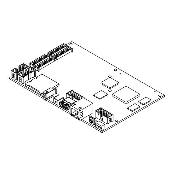
Specifications
Figure 1. NI sbRIO-9636
section for more information about the
Advertisement
Table of Contents

Subscribe to Our Youtube Channel
Related Manuals for National Instruments sbRIO-9605


Summary of Contents for National Instruments sbRIO-9605
- Page 1 NI sbRIO-9623/9626/9633/9636 Single-Board RIO OEM Devices This document provides dimensions, pinouts, connectivity information, and specifications for the National Instruments sbRIO-9605, sbRIO-9606, sbRIO-9623, sbRIO-9626, sbRIO-9633 and sbRIO-9636. The devices are referred to inclusively in this document as the NI sbRIO device.
- Page 2 Product misuse can result in a hazard. You can compromise the safety protection built into the product if the product is damaged in any way. If the product is damaged, return it to National Instruments for repair. What You Need to Get Started This section lists the software and hardware you need to start programming the NI sbRIO device.
- Page 3 8 J505, RJ-45 Ethernet Port 18 DDR Memory 9 W501, RS-232 Serial (COM1) 19 J1, RIO Mezzanine Card Connector 10 Reset Switch Figure 2. All possible components on the NI sbRIO Device © National Instruments 3 NI sbRIO-960x/962x/963x OEM Instructions & Specifications...
- Page 4 Table 1 describes the I/O and other components populated on each NI sbRIO device. Table 1. I/O and other components available on NI sbRIO devices NI sbRlO device Memory FPGA sbRIO-9605 256 MB 128 MB — — — — LX25 —...
- Page 5 0.15 mm. For example, if you are using a SEAM-40-03.0-S-06-2 connector to mate to the RMC connector (SEAF-40-06.5-S-06-2), the required standoff height is 3.0 mm + 6.5 mm + 0.15 mm = 9.65 mm. Standoffs of this height are available from National Instruments (NI 153166-12) or Samtec (SO-0965-03-02-L-N). Consult Samtec for alternative heights and options.
- Page 6 NAND Flash Pin 2 18.13 (.714) Pin 2 Pin 1 17.17 (.676) 0.64 (.025) Pin 1 0 (.000) 1 Back of Front Panel Figure 3. NI sbRIO-9605/9606 Primary-Side Dimensions in mm (in.) NI sbRIO-960x/962x/963x OEM Instructions & Specifications 6 ni.com...
- Page 7 26.67 (1.050) 0 (.000) 73.63 (2.899) 1 Holes and Keepouts Sized for M3 Standoff (4.5 mm Hex) or 4-40 Standoff (3/16-in. Hex) Figure 4. NI sbRIO-9605/9606 Secondary-Side Dimensions in mm (in.) © National Instruments 7 NI sbRIO-960x/962x/963x OEM Instructions & Specifications...
- Page 8 Figure 5 shows the dimensions of the primary side of the NI sbRIO device. FPGA Processor 84.51 (3.327) 77.60 (3.055) 74.24 (2.923) Pin 1 69.95 (2.754) Pin 2 DDR Memory Pin 1 59.18 (2.330) Pin 2 49.96 (1.967) Pin 2 Pin 1 NAND Flash Pin 2...
- Page 9 3.18 (0.125) 26.67 (1.050) 0 (0.000) 1 Holes and Keepouts Sized for M3 Standoff (4.5 mm Hex) or 4-40 Standoff (3/16-in. Hex) Figure 6. NI sbRIO-9623/9633/9626/9636 Secondary-Side Dimensions in mm (in.) © National Instruments 9 NI sbRIO-960x/962x/963x OEM Instructions & Specifications...
- Page 10 2 Minimum Keepaway for RIO Mezzanine Card Components 3 4-40 threads, Maximum Torque of 0.41 N · m (3.6 lb · in.) Figure 7. NI sbRIO-9605/9606 Front Dimensions in mm (in.) Figure 8 shows the dimensions of the front of the NI sbRIO device.
- Page 11 7.62 mm (0.300 in.) from the surface of the secondary side. Max Component Height = 4.06 (0.160) 31.75 (1.250) Max Component Height = 17.27 (0.680) Figure 9. NI sbRIO-9605/9606 Maximum Component Height of Primary Side in mm (in.) © National Instruments 11 NI sbRIO-960x/962x/963x OEM Instructions & Specifications...
- Page 12 96.52 (3.8) Max Component Height = 9.53 (0.375) Max Component Height = 4.06 (0.160) 31.75 (1.250) Max Component Height = 17.27 (0.680) Figure 10. NI sbRIO-9623/9633/9626/9636 Maximum Component Height of Primary Side in mm (in.) NI sbRIO-960x/962x/963x OEM Instructions & Specifications 12 ni.com...
- Page 13 Max Component Height = 7.62 (0.300) 10.16 (.400) 60.96 (2.400) 11.43 (.450) Max Component Height = 6.15 (0.242) Figure 11. NI sbRIO-9605/9606 Max Component Height of Secondary Side in mm (in.) © National Instruments 13 NI sbRIO-960x/962x/963x OEM Instructions & Specifications...
- Page 14 10.16 (.400) 60.96 (2.400) Max Component Height = 7.62 (0.300) 11.43 (.450) Max Component Height = 6.15 (0.242) Figure 12. NI sbRIO-9623/9633/9626/9636 Max Component Height of Secondary Side in mm (in.) NI sbRIO-960x/962x/963x OEM Instructions & Specifications 14 ni.com...
- Page 15 Maintain a minimum keepaway distance of 7.62 mm (0.300 in) when mounting NI sbRIO devices with an RMC connector, and a minimum keepaway distance of 6.15 mm (0.242 in.) when mounting NI sbRIO devices without an RMC connector. © National Instruments 15 NI sbRIO-960x/962x/963x OEM Instructions & Specifications...
- Page 16 Mating the NI sbRIO Device to a RIO Mezzanine Card This section applies only to the following NI sbRIO devices: • NI sbRIO-9605 • NI sbRIO-9623 • NI sbRIO-9606 • NI sbRIO-9626 1 M3 or 4-40 Standoff (Not Included) 3 Example RMC (Not Included)
- Page 17 Investigate and remove any current differences. Connector Pinouts The following figures show the pinouts of the I/O connectors on the NI sbRIO device. Power Connector Pin 1 Figure 15. Pinout of the Power Connector © National Instruments 17 NI sbRIO-960x/962x/963x OEM Instructions & Specifications...
- Page 18 RS-232/CAN Connectors W501, RS-232 (COM1) SHIELD 10 9 Pin 1 W500, CAN 0 SHIELD CAN0_H V– (GND) SHIELD V– (GND) CAN0_L Pin 1 W503, RS-232 (COM2) SHIELD 10 9 W502, RS-485 (COM3) SHIELD TXD– Pin 1 TXD+ RXD– RXD+ Pin 1 Figure 16.
- Page 19 D GND 45 46 DIO1 D GND 47 48 D GND DIO27 47 48 DIO2 49 50 D GND 49 50 DIO3 Figure 17. Pinout of DIO and MIO Connectors © National Instruments 19 NI sbRIO-960x/962x/963x OEM Instructions & Specifications...
- Page 20 Card connector, indicating the pin number and corresponding function. Users interested in additional processor functionality such as serial, CAN, USB, Note or Ethernet should contact a local National Instruments representative for custom design opportunities. A non-recurring engineering charge (NRE) may apply. Note Reserved and unused lines should be left disconnected on RIO Mezzanine Cards.
- Page 21 Pin 1 98.40 (3.000) 96.75 (3.809) 0 (.000) 0 (.000) Figure 18. RMC Connector Location and Dimensions on Example RIO Mezzanine Card © National Instruments 21 NI sbRIO-960x/962x/963x OEM Instructions & Specifications...
- Page 22 Table 3. RIO Mezzanine Card Connector Pinout 1-RESERVED 2-RESERVED 3-RESERVED 4-RESERVED 5-RESERVED 6-RESERVED 7-RESERVED 8-RESERVED 9-RESERVED 10-RESERVED 11-RESERVED 12-RESERVED 13-RESERVED 14-RESERVED 15-RESERVED 16-RESERVED 17-GND 18-RESERVED 19-RESERVED 20-RESERVED 21-RESERVED 22-RESERVED 23-GND 24-RESERVED 25-RESERVED 26-RESERVED 27-RESERVED 28-RESERVED 29-USB_D+ 30-GND 31-RESERVED 32-RESERVED 33-RESERVED 34-RESERVED 35-USB_D–...
- Page 23 30 pF on the RST# line of a RIO Mezzanine Card. This includes the RMC Connector, traces, vias, and device pins. Refer to 3.3 V Digital I/O on RIO Mezzanine Card Connector in the Specifications section for output logic levels. © National Instruments 23 NI sbRIO-960x/962x/963x OEM Instructions & Specifications...
- Page 24 FPGA_CONF The FPGA_CONF signal asserts high when the FPGA has been programmed. When the FPGA is unconfigured the signal is floating. A pulldown resistor is required when using this signal to ensure it returns to ground. 3.3 V Digital I/O The NI sbRIO device provides 3.3 V digital I/O via the RIO Mezzanine Card connector and the 50-pin IDC headers.
- Page 25 The following figure shows the circuitry for one AI channel on the NI sbRIO-9623/9633. AI <0..15> AI Data AI GND Input Range Selection Figure 21. Single-Ended Analog Input on the NI sbRIO-9623/9633 © National Instruments 25 NI sbRIO-960x/962x/963x OEM Instructions & Specifications...
- Page 26 The following figure shows the circuitry for one AI channel on the NI sbRIO-9626/9636. AI <0..15> DIFF, RSE AI Data PGIA Input Range AI GND Selection AI Terminal Configuration Selection Figure 22. Single-Ended Analog Input on the NI sbRIO-9626/9636 Analog Input Range An input range is a set of input voltages that an analog input channel can digitize with the specified accuracy.
- Page 27 Refer to the NI sbRIO-9626/9636 section for the maximum working voltage for each range. If any of these conditions are exceeded, the input voltage is clamped until the fault condition is removed. © National Instruments 27 NI sbRIO-960x/962x/963x OEM Instructions & Specifications...
- Page 28 The capacitance of the cable can also increase the settling error. National Instruments recommends using individually shielded twisted-pair wires shorter than 2 m to connect AI signals to the device. Refer to the...
- Page 29 Floating Grounded Signal Source Signal Source AI GND AI GND = 100 kΩ - 1MΩ Figure 23. Differential Connections with Floating and Grounded Signal Sources © National Instruments 29 NI sbRIO-960x/962x/963x OEM Instructions & Specifications...
- Page 30 Connecting Analog Input Signals Table 7 summarizes the recommended input configuration for both types of signal sources. Table 7. NI sbRIO Analog Input Configuration Floating Signal Sources (Not Connected to Building Ground-Referenced Ground) Signal Sources Examples: Example: • Ungrounded thermocouples •...
- Page 31 In the single-ended modes, more electrostatic and magnetic noise couples into the signal connections than in DIFF configurations. The coupling is the © National Instruments 31 NI sbRIO-960x/962x/963x OEM Instructions & Specifications...
- Page 32 result of differences in the signal path. Magnetic coupling is proportional to the area between the two signal conductors. Electrical coupling is a function of how much the electric field differs between the two conductors. With this type of connection, the NI sbRIO device rejects both the common-mode noise in the signal and the ground potential difference between the signal source and the device ground.
- Page 33 (sum) of the two resistors. If, for example, the source impedance is 2 kΩ and each of the two resistors is 100 kΩ, the resistors load down the source with 200 kΩ and produce a –1% gain error. © National Instruments 33 NI sbRIO-960x/962x/963x OEM Instructions & Specifications...
- Page 34 Bias Resistors (see text) Floating Instrumentation Signal Amplifier Source – PGIA AI– Measured – Voltage – Bias Current Return Paths Input Multiplexers AI GND I/O Connector Figure 26. Differential Connections for Floating Signal Sources with Balanced Bias Resistors Both inputs of the PGIA require a DC path to ground in order for the PGIA to work.
- Page 35 Figure 28 shows an AO channel on the NI sbRIO-9623/9633. AO 0-5 V Nominal AO GND NI sbRIO - 9623/33 Analog Output Figure 28. Analog Output Channel on NI sbRIO-9623/9633 © National Instruments 35 NI sbRIO-960x/962x/963x OEM Instructions & Specifications...
- Page 36 Figure 29 shows an AO channel on the NI sbRIO-9626/9636. Gain and 10 V Nominal /– Protection AO GND NI sbRIO - 9626/36 Analog Output Figure 29. Analog Output Channel on NI sbRIO-9626/9636 Analog Output Startup and Initialization The analog output on the NI sbRIO device does not get powered until the first time the FPGA is loaded after applying board power.
- Page 37 To turn these startup options on or off, select the controller under Remote Systems in the MAX configuration tree, then select the Controller Settings tab. Refer to the MAX Help for information about the startup options and how to configure the controller. © National Instruments 37 NI sbRIO-960x/962x/963x OEM Instructions & Specifications...
- Page 38 These options determine how the FPGA behaves when the device is reset in various conditions. Use the RIO Device Setup utility to select reset options. Access the RIO Device Setup utility by selecting Start» All Programs»National Instruments»NI-RIO»RIO Device Setup. Table 8. NI sbRIO Reset Options Reset Option...
- Page 39 This requirement does not mean that every node on the bus should have a termination resistor; only the two nodes at the far end of the cable should have termination resistors. © National Instruments 39 NI sbRIO-960x/962x/963x OEM Instructions & Specifications...
- Page 40 Figure 31 shows a simplified diagram of a CAN bus with multiple CAN nodes and proper termination resistor (Rt) locations. Bus Cable Length CAN_H CAN_H Node Node CAN_L CAN_L Stub Length Node Node Figure 31. CAN Bus Topology and Termination Resistor Locations Cable Specifications Cables should meet the physical medium requirements specified in ISO 11898, shown in Table 9.
- Page 41 Refer to Figure 32 and Table 11 for USB pin locations and signal descriptions. Pin 4 Pin 1 Figure 32. USB Port Pin Locations © National Instruments 41 NI sbRIO-960x/962x/963x OEM Instructions & Specifications...
- Page 42 Ground Using the System Clock to Provide Data Timestamps At startup, the system clock of the NI sbRIO-9605/9606 resets to January 1, 1970, 12:00 a.m. (midnight), unless VBAT is implemented on the RMC. For information about synchronizing the system clock with an SNTP time...
- Page 43 LED turns off, the POST is complete. The NI sbRIO Device indicates specific error conditions by flashing the Status LED a certain number of times every few seconds, as shown in Table 12. © National Instruments 43 NI sbRIO-960x/962x/963x OEM Instructions & Specifications...
- Page 44 Table 12. Status LED Indications Number of Flashes Every Few Seconds Indication The device has detected an error in its software. This usually occurs when an attempt to upgrade the software is interrupted. Reinstall software on the device. Refer to the Measurement & Automation Explorer Help for information about installing software on the device.
- Page 45 LabVIEW run-time engine to load. Specifications Unless otherwise noted, the following specifications are typical for the range –40 to 85 °C for the NI sbRIO device. Processor Speed NI sbRIO-9605/9606/9623/9626 9633/9636..........400 MHz Memory NI sbRIO-9605/9623/9633 Nonvolatile memory ....... 256 MB System memory ......
- Page 46 Note practices for using nonvolatile memory, go to and enter the Info Code ni.com/info SSDBP FPGA NI sbRIO-9605/9623/9633 FPGA type ........Xilinx Spartan-6 LX25 Number of flip-flops......30,064 Number of 6-input LUTs....15,032 Number of DSP48s......38 Available block RAM......936 kbits Number of DMA channels ....5 NI sbRIO-9606/9626/9636 FPGA type ........Xilinx Spartan-6 LX45...
- Page 47 Internal RTC Accuracy ..........200 ppm; 35 ppm @ 25 °C VBAT input range........3.0 to 3.6 V (Nominal); 3.7 V Max SD Port SD card support........SD and SDHC standards © National Instruments 47 NI sbRIO-960x/962x/963x OEM Instructions & Specifications...
- Page 48 3.3 V Digital I/O on RIO Mezzanine Card Connector Number of DIO channels......96 Max tested current per channel....±3 mA Max total current, all lines ......288 mA Note The performance of the RMC DIO lines is bounded by the FPGA, signal integrity, the application timing requirements, and the RMC design.
-
Page 49: Table Of Contents
Number of channels ....... 16 single-ended or 8 differential ADC Resolution........16 bits Maximum aggregate sampling rate..200 kS/s Input range ..........±10 V, ±5 V, ±2 V, ±1 V © National Instruments 49 NI sbRIO-960x/962x/963x OEM Instructions & Specifications... -
Page 50: Input Impedance
Maximum working voltage (signal + common mode) Range Working voltage 10 V ±11 V ± 10.5 V ± 9 V ± 8.5 V Input impedance Powered on ........> 1 GΩ in parallel with 100 pF Powered off/overload ......2.3 kΩ min Overvoltage protection Powered on ........ -
Page 51: Input Bandwidth (-3 Db)
1 V Range 2 V Range 5 V Range 10 V Range 1000 10000 Frequency (Hz) –1 –2 –3 –4 –5 –6 –7 –8 1000 10000 100000 1000000 Frequency (Hz) © National Instruments 51 NI sbRIO-960x/962x/963x OEM Instructions & Specifications... - Page 52 100000 10000 1000 1000 10000 100000 Source Impedance (Ω) Analog Output Characteristics NI sbRIO-9623/9633 Number of channels........4 DAC resolution........12 bits Max update rate ........336 kS/s Range ............0–5 V Output impedance........13 Ω typical, 27 Ω max Current drive...........±1 mA / channel max. Protection..........Short-circuit to ground Power-on state ........0 V...
-
Page 53: Ni Sbrio-9626/9636
This is the maximum update rate when running one AO channel in a loop with the FPGA top-level clock set to 40 MHz. When the analog output initializes, a glitch occurs for about 20 µs, peaking at 1.3 V, typical. © National Instruments 53 NI sbRIO-960x/962x/963x OEM Instructions & Specifications... - Page 54 AO accuracy Percent of Reading Percent of Range Measurement Conditions (Gain Error) (Offset Error) Typical (25 °C, ±5 °C) 0.09% 0.02% Max (–40 to 85 °C) 0.50% 0.20% Range is 10 V. Gain drift..........23 ppm of reading/°C Offset drift ..........5.4 ppm of range/°C INL............±194 ppm of range, max DNL ............±16 ppm of range, max Capacitive drive ........1.5 nF, typical...
- Page 55 ........Total 3.3 V current × 3.3 V / 0.8 Maximum P 3.3V ........Total USB current × 5 V / 0.9 Maximum P ........Total SD current × 3.3 V / 0.8 Maximum P © National Instruments 55 NI sbRIO-960x/962x/963x OEM Instructions & Specifications...
- Page 56 NI sbRIO-9623/9633 .......Total AO current × 5 V / 0.5 NI sbRIO-9626/9636 .......Total AO current × 15 V / 0.5 Table 13. NI sbRIO Device Maximum Power Levels Model 3.3V NI sbRIO-9605 5.66 W NI sbRIO-9606 8.10 W 2.78 W 1.79 W...
- Page 57 NI sbRIO-9605 Power consumption while sourcing RMC......... 19.1 W Max NI sbRIO-9606 Power consumption while sourcing RMC......... 25.4 W Max NI sbRIO-9623 Power consumption while sourcing RMC......... 21.7 W Max NI sbRIO-9626 Power consumption while sourcing RMC......... 29.9 W Max NI sbRIO-9633 Power consumption......
- Page 58 Some systems may require a heat sink or air flow to remain within the maximum allowed temperature ranges. A heat spreader is available from National Instruments that you can mount on the NI sbRIO device. The heat spreader is NI 9695, part number 153901-01.
- Page 59 Instruments WEEE initiatives, and compliance with WEEE Directive 2002/96/EC on Waste and Electronic Equipment, visit ni.com/environment/weee National Instruments (RoHS) National Instruments RoHS ni.com/environment/rohs_china (For information about China RoHS compliance, go to ni.com/environment/rohs_china © National Instruments 59 NI sbRIO-960x/962x/963x OEM Instructions & Specifications...
- Page 60 For patents covering National Instruments products/technology, refer to the appropriate location: Help»Patents in your software, the patents.txt file on your media, or the National Instruments Patent Notice at ni.com/patents. Refer to the Export Compliance Information at ni.com/legal/ export-compliance for the National Instruments global trade compliance policy and how to obtain relevant HTS codes, ECCNs, and other import/export data.
Need help?
Do you have a question about the sbRIO-9605 and is the answer not in the manual?
Questions and answers