Table of Contents
Advertisement
Quick Links
Advertisement
Table of Contents

Related Manuals for Simpli Home 3AXCBUR-004


Summary of Contents for Simpli Home 3AXCBUR-004
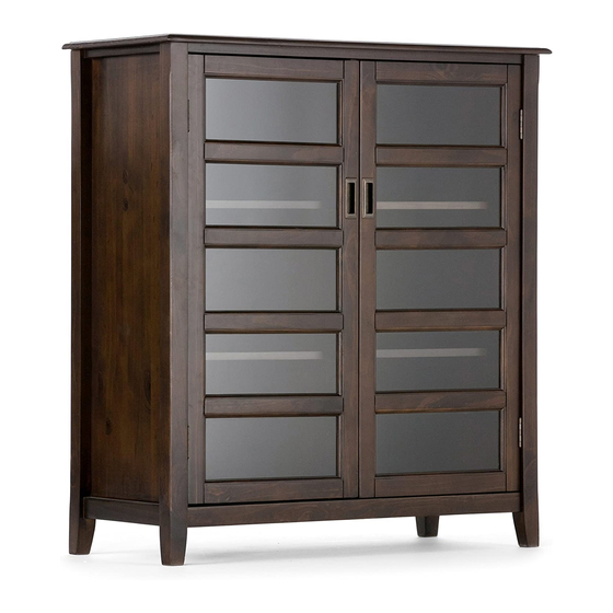
- Page 1 MEDIUM STORAGE CABINET 1/14...
- Page 2 DO NOT RETURN FOR REPLACEMENT PARTS OR OTHER INQUIRIES PLEASE CONTACT US PLEASE ENSURE TO HAVE THE MODEL # FROM THE PACKAGING OR INSTRUCTION BOOKLET 2/14...
-
Page 3: Safety Information
IMPORTANT : Please read this manual carefully before beginning assembly of this product Keep this manual for future reference. SAFETY INFORMATION Identify all the parts and hardware. Do not discard of the packaging until you have checked that you have all of the parts and hardware required. Hardware package may have spare parts. -
Page 4: Pre-Assembly Information
PRE-ASSEMBLY INFORMATION PARTS DESCRIPTION SIDE BOTTOM SHELF QTY 1 PAIR QTY 1 QTY 1 CENTRE SUPPORT DOOR CABINET SHELF QTY 1 QTY 1 PAIR QTY 4 BACK PANEL QTY 1 PAIR NEED HELP? For help with assembly or if you are missing a part, Please call customer service 4/14... -
Page 5: Hardware Description
PRE ASSEMBLY INFORMATION HARDWARE DESCRIPTION ALLEN KEY SCREW WOOD DOWEL M6 X 30 mm ALLEN KEY Ø8 X 30 mm QTY 18 QTY 1 QTY 4 PHILLIPS SCREW ROUND HEAD PHILLIPS SCREW M4 X 15 mm M3 X 12 mm SHELF SUPPORT QTY 24 QTY 28... - Page 6 COMPONENTS – KEY DIAGRAM 6/14...
- Page 7 ASSEMBLY STEP 1 1. Insert 4 Dowels 2 into pre-drilled holes on Bottom Shelf C ( 2 / each Side ). 2. Align Dowels 2 on Bottom Shelf C with pre-drilled holes on Sides A . 3. Attach Sides A to Bottom Shelf C using 6 Allen Key Screws 1 ( 3 Screws / each Side ). 4.
- Page 8 ASSEMBLY STEP 2 1. Attach Centre Support D to Bottom Shelf C using 3 Allen Key Screws 1 . 2. Use Allen key 3 to tighten. Do not over-tighten. Note: Prior to inserting Allen Key Screws 1 , ensure that the direction the holes for the Shelf Supports 6 on Centre Support D and the holes for the Shelf Supports 6 on the Side A are compatible.
- Page 9 ASSEMBLY STEP 3 1. Attach Top B to Centre Support D and Side A using 9 Allen Key Screws 1 ( 3 Screws / each part ). 2. Use Allen key 3 to tighten. Do not over-tighten. 9/14...
- Page 10 ASSEMBLY STEP 4 NOTE: The screwdriver is not included in the hardware pack. 1. Attach Doors E to Sides A using Phillips Screws 5 . 2. Attach Magnet Plates 7 into guide holes on bottom corner of Doors E using Phillips Screws 5 .
- Page 11 ASSEMBLY STEP 5 NOTE: The screwdriver is not included in the hardware pack. 1. Attach Back Panel G to back frame of cabinet using Phillips Screws Round Head 4 into pre-drilled guide holes. 2. Use Phillips screwdriver to tighten screws. Do not over tighten. 11/14...
- Page 12 ASSEMBLY STEP 6 1. Use 4 Shelf Supports 6 for each Shelf F in desired location. 2. 2 Shelf Supports 6 may be used on back top of each Shelf F as a tipping restraint . 12/14...
- Page 13 ASSEMBLY STEP 7 NOTE: The screwdriver is not included in the hardware pack. 1. To attach Tipping Restraint 8 , follow instructions on Tipping Restraint package. When you determined the location for your unit, install the Furniture Tipping restraint. Carefully follow the instructions contained on the package. 13/14...
-
Page 14: Warranty
WARRANTY Thank you for purchasing our product. These products have been made to demanding, high-quality standards and are guaranteed for domestic use against manufacturing faults for a period of 12 months from the date of purchase. This warranty does not affect your statutory rights. In case of any malfunction of your product (f ailure, missing parts, etc.) or by email...
Need help?
Do you have a question about the 3AXCBUR-004 and is the answer not in the manual?
Questions and answers