Table of Contents
Advertisement
Quick Links
SPS5
9 SERIES PAGING SYSTEM MANUAL
V
Phone: 1-972-479-1702
E-mail:
sales@wirelessmessaging.com
TABLE OF CONTENTS
INTRO TO THE V9 PAGING SYSTEMS ........................................................................................... 3
................................................................................................................................ 3
............................................................................................................................. 4
Current Systems ............................................................................................................................ 4
Legacy Systems ............................................................................................................................. 4
Features & Capabilities ................................................................................................................. 4
FIRST TIME INSTALLATION ......................................................................................................... 9
V9 ENCODER SETUP SOFTWARE GUIDE .....................................................................................10
................................................................................................................................ 12
......................................................................................................................................... 13
1. Pager Families ......................................................................................................................... 13
2. Group Paging .......................................................................................................................... 14
3. Canned Msgs ........................................................................................................................... 14
4. Settings .................................................................................................................................... 15
6. Discover ................................................................................................................................... 20
WEB CONFIGURATION GUIDE ...................................................................................................20
........................................................................................................................................ 21
.................................................................................................................................. 22
................................................................................................................................... 24
WAVEWARE TECHNOLOGIES INC. V2.0 OCT 2019
Toll Free: 1-800-373-1466
Technical Support:
........................................................................................... 7
...................................................................................................................... 10
................................................................................................................. 20
Fax: 1-972-479-1735
support@wirelessmessaging.com
[1]
Advertisement
Table of Contents

Related Manuals for WaveWare SPS5 V9 Series

Summary of Contents for WaveWare SPS5 V9 Series
-
Page 1: Table Of Contents
SPS5 9 SERIES PAGING SYSTEM MANUAL WAVEWARE TECHNOLOGIES INC. V2.0 OCT 2019 Phone: 1-972-479-1702 Toll Free: 1-800-373-1466 Fax: 1-972-479-1735 E-mail: sales@wirelessmessaging.com Technical Support: support@wirelessmessaging.com TABLE OF CONTENTS INTRO TO THE V9 PAGING SYSTEMS ................... 3 ..........................3 YSTEM VERVIEW & F .......................... - Page 2 APPENDIX C – TAP CHECKSUM CALCULATION ................36 APPENDIX D – TAP EMBEDDED CONTROL CHARACTERS .............37 APPENDIX E – TAP RESPONSE CODES ..................38 APPENDIX F – EXTENDED ID PROCESSING ..................38 APPENDIX G – WAVEWARE INTERFACE SPECIFICATIONS ............40 ........................40 AGING ESSAGE ORMAT .......................
-
Page 3: Intro To The V9 Paging Systems
INTRO TO THE V9 PAGING SYSTEMS The SPS5 v9 series of paging systems transmit POCSAG messages and/or tones to Paging Data Receivers (PDRs). These messages can come in various paging protocols, or in various methods of delivery such as automatic transmission, manual typing of messages, and it can also receive messages from other devices as long as the paging data protocol is compatible with an SPS-5v9 system. -
Page 4: Models & Features
• UHF & VHF BANDS WaveWare has FCC Shared-Use Licenses for different frequencies in the UHF band (450-470 MHz). For VHF or any UHF frequencies we do not own, we can handle your site’s application to the FCC for a fee. This only applies to U.S. installations. - Page 5 Alphanumeric (Text), Numeric and Tone/Vibe Only Paging Message Formats o Multiple Tone and Vibration Patterns o Batch Message Delivery up to 32 messages, with 240 Characters per Message (500 Characters in WaveWare Paging Protocol) • MULTIPLE PAGING PROTOCOLS customizable for each connection. The compatible protocols are: o TAP v1.8: A bidirectional protocol that has the most robust and secure communications...
- Page 6 IDs each, Stored in Non-Volatile EEPROM Memory. The Pager Database is “Not Required” for WaveWare Protocol, Scope Protocol, the Extended Pager ID Method, or Pager ID as Cap Code Mode. Windows Software, called WaveWare SPS-5 v9 “Paging Encoder Setup” is provided for Pager Database Programming, Com Port Settings, Ethernet settings, Range Testing, and General Messaging.
-
Page 7: Obtaining Pagers For Your Paging System
Alphanumeric, Numeric and Tone/vibe and Wireless Message Centers. WaveWare Compatible Paging Receivers can be obtained from many sources including WaveWare Technologies. The Paging Receivers that you obtain for use with WaveWare v9 series paging systems should meet the following basic specifications: •... - Page 8 • BAUD RATE: Each paging receiver must have a baud rate of 512, 1200, or 2400 to be used. Different baud rates can be used in a single installation. • CAP CODES: Each paging receiver must have at least one active cap code programmed into it. Figure 4: POCSAG Device Examples ALPHANUMERIC PAGERS NUMERIC PAGERS...
-
Page 9: First Time Installation
FIRST TIME INSTALLATION Your WaveWare v9 Series Paging System includes: 1 Transmitter Unit, a “Rubber Duck” Antenna, 1 RS-232 Cable, 1 Ethernet Cable (where applicable), Mounting Screws/Plastic Anchor Kit and a Power Supply. To install the paging system, please follow these steps: ATTACH THE “RUBBER DUCK”... -
Page 10: V9 Encoder Setup Software Guide
V9 ENCODER SETUP SOFTWARE GUIDE When using WaveWare’s Paging Encoder Setup v9, all system communications are sent through a serial connection. Since most PCs do not have serial ports these days, this is accomplished by using USB ports via a USB-Serial Adapter. - Page 11 • COM PORT – This is a list of the current serial or USB-serial connections on your PC. • BAUD RATE – This is a list of valid serial port transmission rates. • PARITY – These are compatible data binary formats sent through the serial connection. PAGE 14 HAS A STEP-BY-STEP PROCESS OF CONNECTING TO THE CORRECT COM PORT: 1.
-
Page 12: The Main Menu
TEST ENCODER window. • PAGING ENCODER SETUP GUIDE – Opens this guide. • SPS5 V9 SERIES MANUAL – Opens the manual for the SPS5 v9 series of paging systems. • ABOUT PAGING ENCODER SETUP – Shows the splash screen. • [12]... -
Page 13: Functions
FUNCTIONS This section will cover the main functions of the Paging Encoder Setup V9 Software (fig. Figure 9: Main Functions 1. PAGER FAMILIES PAGER FAMILIES (fig. 10) displays the current database’s list of valid pager IDs, capcodes, and messaging formats used for transmitting pages, and each row in the window is a separate Pager Family entry. -
Page 14: Group Paging
PAGER TYPE – Changes the message type pagers receive from this Pager Family. FUNCTION CODE – Sets the function code used by a pager when it receives a page from this Pager Family. Some pagers refer to function codes as letters. In this case: 1=A, 2=B, 3=C, and 4=D. -
Page 15: Settings
Figure 12: Canned Msgs. Window 4. SETTINGS SERIAL SETTINGS Figure 13: Serial Settings Tab [15]... - Page 16 PAGING PROTOCOL – Determines the data format the Encoder is looking for when the Host Device sends paging data. [NON-]/VERBOSE MSGS. – Controls how paging system replies are sent to a host device. BAUD RATE – Controls the transmission rate the serial port input is looking for from a host device. PARITY –...
- Page 17 USE DHCP – Controls if the IP address and network is set automatically or if it is entered manually. IP ADDRESS – The network address of the paging system. SUBNET MASK – Sets how your network is sub-divided. PRIMARY/SECONDARY DNS –...
-
Page 18: Test Encoder & Range Test
CARRIER SIGNAL DETECTION – Controls if the paging system will check for carrier signals. INCREMENT CAPCODES BY 8 – Changes whether the capcodes number sequentially or by 8 for each ID in PAGER FAMILIES. PAGING SITE LICENSE CALL SIGN – Issued to paging systems so the FCC knows it’s a valid paging site. SERIAL PORT RESET OF TIMED PAGING –... - Page 19 – Sets the function code manually. Only used with Scope protocol testing. RF DATA RATE – Sets the data rate manually. Used with Scope and WaveWare protocol testing. SEND – Pushes a single page to the radio transmitter using the parameters set in Test Encoder.
-
Page 20: Discover
This is usually your Ethernet connection if you also have a Wifi connection. When you click the DISCOVER button, a list will populate containing all the IP addresses and types of WaveWare products on your network (fig. -
Page 21: Messaging
Click on the IP ADDRESS that is matched with the SPS5 v9E. b. Discover & Reset Tool Method: i. Download the WaveWare Discover & Reset Tool from our website at https://www.wirelessmessaging.com/waveware-discover-reset-tool and open it. ii. Click the DISCOVER BUTTON. -
Page 22: Pager Families
PAGER FAMILIES The Pager Families tab (fig. 17) functions in the exact same way as the Paging Encoder Setup software, but it does have visual differences. It defines what IDs and capcodes will be used with the paging system as well as a few messaging format options. Figure 17: Pager Families Tab [22]... - Page 23 FAMILY – A row designation for each Pager Family. ENABLE – Controls if a Pager Family is checked when paging data is received from a HOST DEVICE. PAGER QTY – Sets the range of ID and capcode pairings. It can be set from 1-999. START ID –...
-
Page 24: Pager Groups
PAGER GROUPS PAGER GROUPS (fig. 18) shows all of the current pager IDs bound together by a common group ID. Figure 18: Pager Groups Tab GROUP ACTIVE – Controls if the group is checked when paging data is received from a Host Device. GROUP ID –... -
Page 25: Predefined Msg
TIMER MESSAGE – The message, created in Canned Msgs, that pages to the associated Paging Group when the timer’s 2 minutes have passed. CLEAR ALL – Resets all Pager Groups to default values. SAVE CHANGES – Writes the current state of the Pager Families configuration to the paging encoder. If you switch tabs before saving, all changes will be lost. -
Page 26: Serial Port
SERIAL PORT The Serial Port tab (fig. 20) allows users to program the serial port settings through the web configuration, but you have to reboot the paging system for the changes to take effect. Figure 20: Serial Port Tab PROTOCOL –... -
Page 27: Network
NETWORK Figure 21: Network Tab SPS-5 V9E MAC ADDRESS – The address of the Network Interface Card in the paging system. SPS-5 V9E HOST NAME – The name that appears in the Discover and Reset Tool and on the network. ENABLE DHCP –... - Page 28 GATEWAY IP – The address connecting the paging system’s LAN to other networks. NETWORK ACTIVITY RESETS TIMED PAGING – Controls if a timed group message can be reset. PORT NUMBER FOR IP CONNECTION # – The port a paging system can receive data from a host device. PROTOCOL FOR IP CONNECTION # –...
-
Page 29: Status
INVERT MODULATION DATA – allows messages to be encoded with normal or inverted data encoding. MAXIMUM MESSAGES PER TRANSMISSION – Controls how many messages are sent in a single cycle. STATION IDENTIFIER – Issued to paging systems so the FCC knows it’s a valid paging site. STATION IDENTIFIER INTERVAL –... -
Page 30: Appendix A - Tap Interface Specifications
Settings, for details on serial communication parameters. The SPS5 v9 Series Paging Systems maintain an input buffer which can receive commands from the PC while a page is being transmitted. The input buffer should be able to contain approximately ten paging messages before getting full. -
Page 31: System Identification Command
PAGING SESSION LOGOUT SYSTEM IDENTIFICATION COMMAND The System Identification Command allows installation programs and other software applications to poll serial ports for the existence of a WaveWare v9E Paging Encoder using the STANDARD ATI COMMAND. This can be used for a supervised process... -
Page 32: Paging Session Login
REMOTE ENTRY DEVICE, to initiate communications with the paging system. With the WaveWare v9E Paging Systems, the login process is optional, because, it will automatically login to a host device and process paging messages if it recognizes a properly formatted TAP message block at any point in its operation. Below is a step by step breakdown of the login process. - Page 33 3 digits of the ID field define paging message encoding attributes, while the preceding digits define the pager cap code. Extended ID processing avoids having to configure and check Pager Families in WaveWare SPS5 v9 Series Paging Systems. See Appendix F – Extended ID Processing details on how to format the ID field.
-
Page 34: Paging Session Logout
With the WaveWare v9E Paging System, the logout process is optional. The SPS5 v9 Series Paging System will automatically logout from a host device if the paging system detects a serial disconnection at any point in its operation. -
Page 35: Appendix B - Com Port Settings
20-21) to make these changes as well. Your WaveWare v9E Paging System typically communicates with a PC or other host system via RS- 232 at 9600 Baud, No Parity, 8 data bits, and 1 stop bit. You can configure the paging system for other serial communication parameters. -
Page 36: Appendix C - Tap Checksum Calculation
APPENDIX C – TAP CHECKSUM CALCULATION THE FOLLOWING IS THE VB .NET CODE THAT CREATES THE STRING TO BE SENT TO THE PAGING ENCODER WITH THE CHECKSUM APPENDED TO IT: ‘Functions take any values given to them, execute their section of code, and return a value to the caller. Public Function CreateTapMsg(ByVal PIN As String, ByVal Msg As String) ‘The PIN and Msg values are the Pager Families ID and the message needed to be sent respectively. -
Page 37: Appendix D - Tap Embedded Control Characters
‘Closes the connection between the device running this code and the paging system. End Sub When using WaveWare Protocol it is not necessary to make use of the <SUB> control character for <CR> or <LF>, since the WaveWare protocol doesn’t use either control character in its message format. -
Page 38: Appendix E - Tap Response Codes
<ACK> represents DEC 06, <NAK> represents DEC 21, and <RS> represents DEC 30.) APPENDIX F – EXTENDED ID PROCESSING The WaveWare v9E TAP Interface and COMP2 interfaces support ID field lengths from 1 to 10 digits. THE ID FIELD CAN BE FORMATTED AS FOLLOWS: STANDARD METHOD - ID field lengths from 1 to 4 digits will cause a pager database lookup. - Page 39 THE EXTENDED ID FIELD IS REPRESENTED IN THE FORMAT CCCCCCCERF: CCCCCCC: A 2 to 7 digit numeric value representing a pager cap code. Leading zeroes are optional except in the case of cap codes 8 and 9, which should be represented with at least one leading zero, e.g. 08 or 09. The message encoding type, where “0”...
-
Page 40: Appendix G - Waveware Interface Specifications
RF data rate. The WaveWare Interface supports paging message blocks up to 512 characters in length while the TAP interface supports paging message blocks up to 256 characters in length, group paging, and timed messaging. - Page 41 – Alphanumeric character representing the type of paging message to be transmitted: ALPHANUMERIC, NUMERIC, 1 = ONE BEEP, 2 = TWO BEEPS, 3 = THREE BEEPS, 4 = FOUR BEEPS (alphanumeric pagers). – Numeric character representing the data rate, in bits per second, at which the paging message is to be transmitted: 5 = 512 BPS, 1 = 1200 BPS, 2 = 2400 BPS.
-
Page 42: Response To All Commands
Will send a four beep tone only message at 512 bps to a paging receiver with cap code 0006123. RESPONSE TO ALL COMMANDS The SPS5 v9 Series Paging Systems will respond immediately to all commands, including Paging Message commands, Setup Commands, and Status Commands, by echoing the Paging Message command back to the PC, and appending the echoed command with a status message in one of the following formats: <SOH><ACK>V…V,QQ,D,C,II<EOT>... - Page 43 <SOH><NAK>EE<EOT> The NAK response is sent to the host device immediately following a command if errors occur. <SOH> – used to mark the start of a message. <ACK> – used to indicate acknowledgement of valid reception of a command from the host system. V…V –...
- Page 44 THE POSSIBLE ERROR VALUES ARE: – Invalid Message Type. Indicates a message type other than A, N, 1-4 was transmitted. – Invalid Data Rate. Indicates a data rate other than 5, 1, or 2 was transmitted. – Invalid Cap Code. Indicates an invalid cap code was transmitted. Invalid cap codes are: 0-7, 2007664- 2007671, 2045056-2045063, 2097144+.
-
Page 45: Setup Command
SETUP COMMAND You may program the WaveWare SPS5 v9 Series Paging Systems to monitor for interference using the Carrier Detect mode. If the Carrier Detect mode is turned “ON”, the paging encoder will hold paging messages in queue until an offending carrier signal is no longer detected at the transmission frequency of the paging encoder. -
Page 46: Appendix H - Comp1 Interface Specifications
APPENDIX H – COMP1 INTERFACE SPECIFICATIONS The COMP1 protocol allows raw ASCII data to be sent to all pagers in PAGER GROUP #1 in the SPS5 v9 Series PAGING GROUP DATABASE. The COMP1 interface supports paging message blocks up to 255 characters in length, contact monitoring, and timed messaging. -
Page 47: Appendix I - Comp2 Interface Specifications
(3), or (4). AN EXAMPLE OF COMP2 MESSAGE USING FUNCTION CODE A AND PAGER ID 101 IS: 101A<CR>Test Message<CR> CONTROL CHARACTERS RECOGNIZED BY SPS5 V9 SERIES PAGING SYSTEMS IN COMP2 MODE INCLUDE: CARRIAGE RETURN • – <CR> | 13 LINEFEED •... - Page 48 When using COMP2 protocol, paging systems are controlled using strings formatted as follows: SINGLE MESSAGE EXAMPLE USING CARRIAGE RETURN AS DELIMITER: PagerID<CR>Message<CR> SINGLE MESSAGE EXAMPLE USING TILDE AS DELIMITER: PagerID~Message~ TONE/VIBE ONLY EXAMPLE: PagerID<CR><CR> MULTIPLE MESSAGE EXAMPLE: PagerID1<CR>Message1<CR>PagerID2<CR>Message2<CR> FORCED RESYNCHRONIZATION EXAMPLE: <DEL><DEL><DEL>PagerID<CR>Message<CR>...
-
Page 49: Appendix J - Scope Interface Specifications
If the serial input buffer becomes filled with greater than 600 characters, the paging system will output a hardware or a software flow control response, depending how it is configured. Once the serial input buffer drops below 450 characters, the paging system will use flow control signals to indicate that it is no longer busy and that additional data can be delivered to the serial port. -
Page 50: Response To All Commands
EXAMPLE 1: AN0046180DThis is a test<CR> This sends the message “This is a test” at 512 bps to an alphanumeric pager with Cap Code 0046180. (Note: The POCSAG alphanumeric character set is the entire ASCII 7 bit character set.) EXAMPLE 2: NN0765155B412-3433<CR>... -
Page 51: Appendix K - Timed Messaging Function
RECEPTION OF THE ATI<CR> CONTROL STRING ON THE SERIAL PORT. When programming the WaveWare v9E Paging Encoder’s pager database, each of the ten pager groups of up to 15 pagers per group in the pager database can be associated with the Timed Messaging Function and associated with one of up to 15 configurable predefined messages. -
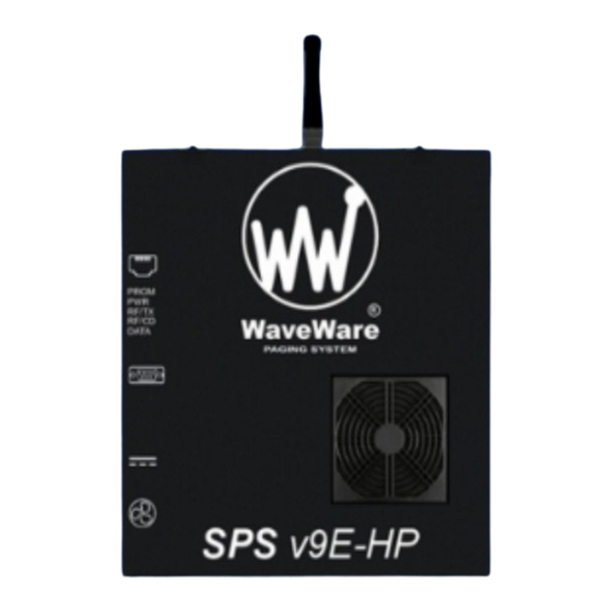
Page 52: Appendix L - Sps5 V9E Systems' Connectors And Indicators
APPENDIX L – SPS5 V9E SYSTEMS’ CONNECTORS AND INDICATORS Figure 25: SPS5 V9E Connectors and Indicators Figure 26: Indicator and Pin-Out Definition Table LED Indicators RS-232 DB-9 Connector Pin-Outs Program: RED LED – Shows when the system is in or (1) CD: Not used. -
Page 53: Appendix M - Site Survey
You may need to monitor for several minutes to determine which channels are busier than others. You can use a PC connected to a SPS5 paging system to perform a range test using the WaveWare Paging Encoder Setup Software (see pg. -
Page 54: Sps5-V9 Series Warranty And Other Information
WaveWare Technologies, Inc. is not liable for damages caused by failure of delivery of messages from WaveWare equipment to pagers, beyond the normal warranted equipment repair or replacement during the warranty period.
Need help?
Do you have a question about the SPS5 V9 Series and is the answer not in the manual?
Questions and answers