MINN KOTA TALON Owner's Manual
Foot switch
Hide thumbs
Also See for TALON:
- User manual ,
- Owner's manual (68 pages) ,
- Installation instructions manual (44 pages)
Table of Contents
Advertisement
Available languages
Available languages
Quick Links
Advertisement
Table of Contents

Subscribe to Our Youtube Channel
Related Manuals for MINN KOTA TALON


Summary of Contents for MINN KOTA TALON
- Page 1 FOOT SWITCH Owner's Manual Compatible with all Bluetooth enabled Talons. ®...
- Page 2 INTRODUCTION THANK YOU Thank you for purchasing the Talon Foot Switch. Intuitive features and wireless control lets you easily raise and lower the Talon spike. Control up to two Talons – independently or simultaneously – from this Bluetooth enabled waterproof switch. Hands free control lets ®...
-
Page 3: Safety Considerations
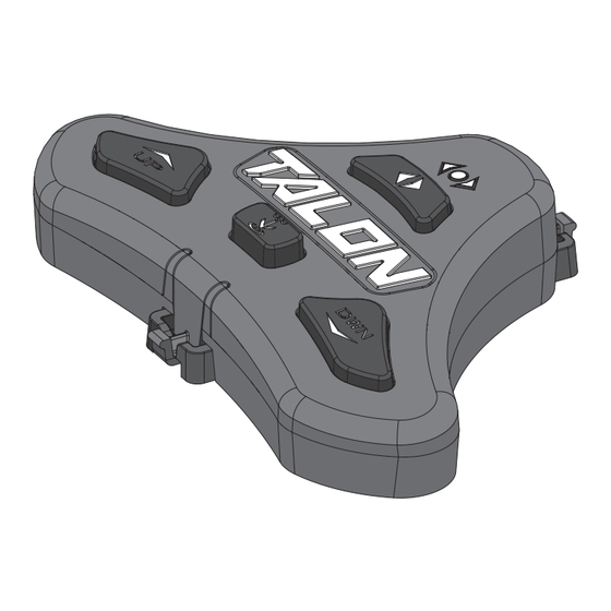
WARNING The Talon should be disconnected from the power source when it is not in use or is off the water. Always disconnect the Talon from battery(s) before cleaning or checking the Talon. In the event of unexpected operation, remove power leads from the battery. - Page 4 FEATURES Talon Selection Indicator LEDs Anchor Mode Selection LED Talon Selection Button / Work Light Button Auto Up Button/ Auto Down Pairing Button Anchor Button/Pairing Mode Button Button NOTE: Specifications subject to change without notice. This diagram is for reference only and may differ from your actual Foot Switch.
-
Page 5: Installation
INSTALLING THE TALON FOOT SWITCH Your new Talon Foot Switch comes complete with all of the hardware you’ll need to install it directly to the deck of your boat. Please review the parts list, mounting considerations and tools needed for installation prior to getting started. - Page 6 Review the Mounting Considerations to determine an acceptable mounting location. Once a location is selected, take the Talon Foot Switch Assembly (Item #A) and remove the Pedestal from the Base by squeezing the Tabs on both sides of the Foot Pedal Foot Switch and pulling the Foot Switch and Pedestal apart.
- Page 7 INSTALLING THE FOOT SWITCH ITEM(S) NEEDED #2 x 3 Double check the Mounting Location. Take the Screws (Item #2) and place one each in the Screws Mounting Holes of the Pedestal. Make sure the Pedestal Mounting Holes line up with the Marked Locations and then use a Drill with #2 Phillips Driving Bit to secure the Pedestal to the Deck of the Boat.
- Page 8 Programming the Mounting Location" section of the Talon Owner's Manual. If the two Talons are already paired together, a Foot Switch can be paired to either Talon. When the pairing process is complete, the Foot Switch will be able to control both Talons.
-
Page 9: Using The Foot Switch
Bottom Mode and Rough Water Mode. LED is lit when the Starboard Talon is selected and the left LED is lit when the Port Talon is selected. Auto Up/Auto Down Buttons Both the right and left arrows are lit when both &... - Page 10 Talon that the Foot Switch is controlling, when 2 Talons are installed on the boat. The selection toggles between a Talon mounted on the Port or Starboard side of the boat, or it can control both Talons at the same time.
- Page 11 Take care that neither you nor other persons approach the Talon too closely, while operating, neither with body parts nor with objects. The Talon is powerful and may endanger or injure you or others. While the Talon is operating, watch out for persons swimming and for floating objects.
- Page 12 Be sure that the Talon is clear of obstructions and persons while retracting. The spaces between the 3 stages of the Talons can create a pinch point. Do not come in contact with the Talon while it is retracting to avoid the pinch point.
- Page 13 Control the Work Light with the Foot Switch The Work Light at the top of the Talon can be either white or blue and toggled between high, medium, or low intensities. To Toggle the Work Light "on", press and hold the...
-
Page 14: Service And Maintenance
CAUTION Before beginning any maintenance work, disconnect the Talon from the battery or if connected to a battery selector switch or power disconnect switch, make sure that it is turned to the "off" position. Failure to disconnect power during maintenance work may result in shock, unexpected operation and/or injury. - Page 15 REPLACING THE REMOTE BATTERY Remove the Battery Cover and the old battery. Battery Cover Replace the battery with a new CR2450 coin cell battery. Note the proper polarity of the battery. O-ring Foot Switch Back NOTICE: The replacement battery must be Battery a model CR2450 coin cell type.
- Page 16 Talons will be cleared. NOTICE: Putting the Foot Switch into Pairing Mode, even if it is accidental, without Pairing the Talon Foot Switch Foot Switch to a Talon will clear all paired Talons. 16 | minnkotamotors.com ©2018 Johnson Outdoors Marine Electronics, Inc.
- Page 17 Email Us You can email our consumer service department with questions regarding your Minn Kota products. To email your question, visit minnkotamotors.com and click on “Support”.
-
Page 18: Environmental Compliance Statement
Minn Kota Talons are not subject to the disposal regulations EAG-VO (electric devices directive) that implements the WEEE directive. Nevertheless never dispose of your Minn Kota Talon in a garbage bin but at the proper place of collection of your local town council. -
Page 19: Industry Canada Compliance
Maximum operating altitude: 10,000 feet RADIO OPERATION TRADEMARKS CONTROLLER Minn Kota®, i-Pilot® and i-Pilot® Link™ are trademarked by or registered trademarks of Johnson Outdoors Marine Electronics, • Frequency band: 2402 MHz to 2480 MHz Inc. • Maximum RF power transmitted: +10 dBm The Bluetooth®... -
Page 20: Parts Diagram & Parts List
TALON FOOT SWITCH The parts diagram and parts list provides Minn Kota® WEEE compliance disassembly instructions. For more information about where you should dispose of your waste equipment for recycling and recovery and/or your European Union member state requirements, please contact your dealer or distributor from which your product was purchased. - Page 21 PARTS DIAGRAM & PARTS LIST Talon Foot Switch Parts List Assembly Part # Description Quantity 2994153 ASSEMBLY,TALON 3 FT SWITCH 2886422 COVER, BATTERY COMPARTMENT ASY Item Part # Description Quantity BATTERY CR2450 ✖ WASHER-RUBBER,W/ADHESIVE ✖ SCREW-2.5MMX8MM DELTA PT TORX ✖...
-
Page 22: Recommended Accessories
UNIVERSAL MODUL AR ADAP TER BR ACKETS It’s easy to choose your bracket, easy to install it and pretty much impossible for anything to stop it. Talon’s Universal Modular Adapter Brackets are built stronger than they have to be, and their innovative modular design lets you put Talon in just the right position on your boat. - Page 23 COMMUTATEUR AU PIED POUR Manuel du propriétaire Compatible avec les tous systèmes Bluetooth activés par Talon.
-
Page 24: Numéro De Série
à remplacer cet appareil. Vous pouvez obtenir du service en appelant Minn Kota au 800 227-6433 ou en retournant votre commutateur au pied pour Talon au Centre de service agréé de Minn Kota. Pour obtenir un service au titre de la garantie, veuillez inclure la preuve d’achat, le numéro de série et la date d’achat. -
Page 25: Consignes De Sécurité
AVERTISSEMENT Veillez à ce que ni vous ni d’autres personnes ne vous approchiez trop près du pieu du Talon, que ce soit seulement avec une partie du corps ou des objets. Le Talon est puissant et pourrait provoquer des situations périlleuses ou des blessures, pour vous ou les autres. -
Page 26: Caractéristiques
CARACTÉRISTIQUES DEL d’indication de la sélection pour Talon DEL de sélection du mode de l’ancre Bouton Sélection du Talon/ Bouton Éclairage de travail Bouton Up (Montée) Bouton Down Bouton Mode de l’ancre automatique/ (Descente) Bouton Couplage automatique/ Bouton Couplage AVIS : Les spécifications peuvent faire l’objet de modifications sans préavis. -
Page 27: Installation
INSTALLATION DU COMMUTATEUR AU PIED POUR TALON Votre nouveau commutateur au pied pour Talon est livré avec toute la quincaillerie qu’il vous faut pour l’installer directement sur le tableau arrière de votre bateau. Avant de commencer, veuillez examiner la liste des pièces et des outils nécessaires à l’installation. - Page 28 Une fois l’emplacement sélectionné, prenez l’ensemble du commutateur au pied pour Talon (article n° A) et retirez le piédestal de la base en serrant les onglets sur chaque côté de la pédale et en séparant le...
- Page 29 INSTALLATION DU TALON ARTICLE(S) REQUIS #2 x 3 Contre-vérifiez l’emplacement du montage. Prenez les vis (article n° 2) et mettez-en une dans chaque trou de montage du piédestal. Veuillez à l’alignement Piédestal des trous de montage avec les emplacements marqués puis utilisez une perceuse avec une mèche Phillips n°...
- Page 30 » de ce manuel du propriétaire Talon. Si les deux Talons sont déjà couplés, on peut coupler un commutateur au pied à un Talon ou à l’autre. Lorsque le processus de couplage est terminé, le commutateur au pied peut contrôler les deux Talons.
- Page 31 Sert à choisir entre le mode Standard, le mode Fond mou et le mode Eaux agitées. Lorsque deux Talons sont couplés dans le système, la DEL droite s’allume lorsque le Talon de tribord Bouton Up (Montée) est sélectionné et la DEL gauche s’allume lorsque automatique / Bouton Down le Talon de bâbord est sélectionné.
- Page 32 Talon contrôlé par le commutateur au pied, lorsque deux Talons sont installés sur le bateau. La sélection passe entre un Talon monté du côté bâbord ou tribord du bateau, ou peut servir à contrôler les deux Talon à la fois.
- Page 33 Lorsque le Talon est en marche, être alerte pour les personnes qui nagent ou les objets flottants. Les personnes dont la capacité à faire fonctionner le Talon est affaiblie par l’alcool, la drogue, les médicaments ou d’autres substances ne sont pas autorisées à...
- Page 34 INSTALLATION DE L’ÉCRAN DE DÉFLEXION D’EAU Rétracter le Talon du commutateur au pied Utilisez les boutons du commutateur au pied pour rétracter l’ancre Talon. Pour rétracter le Talon, appuyez sur le bouton Up (Montée) du commutateur au pied. Bouton Up (Montée)
- Page 35 Contrôler l’éclairage de travail avec le commutateur au pied L’éclairage de travail en haut du Talon peut être de couleur blanche ou bleue et peut être réglé à une intensité élevée, moyenne ou faible. Pour allumer l’éclairage de travail, appuyez sur le Bouton Sélection...
-
Page 36: Service Et Entretien
ATTENTION Avant de commencer tout travail d’entretien, débranchez le Talon de la batterie ou, s’il est connecté à un interrupteur de sélection de batterie ou à un interrupteur de déconnexion d’alimentation, assurez-vous que ce dernier est en position Off (Arrêt). Ne pas débrancher l’alimentation pendant les travaux d’entretien peut mener à... - Page 37 Retirez le couvercle du compartiment de pile et Couvercle du compartiment l’ancienne pile. Remplacez la pile par une pile de pile cellule CR2450. Respectez les indications de Commutateur Joint au pied Arrière polarité de la pile. torique Pile AVIS : La pile de remplacement doit être une pile bouton modèle CR2450.
- Page 38 ÉLIMINATION DE TALON COUPLÉS DU COMMUTATEUR AU PIED Le commutateur au pied a été conçu de manière à ce que tous les Talons couplés puissent être éliminés de la mémoire. Appuyez simultanément sur le bouton Up (Montée) DEL de sélection du DEL d’indication de la...
-
Page 39: Vérification De L'installation
Foire aux questions Notre site Web met à votre disposition des FAQ visant à répondre à toutes vos questions au sujet des produits Minn Kota. Veuillez visiter le site Web minnkotamotors.com, puis cliquer sur « Foire aux questions » pour trouver réponse à vos questions. -
Page 40: Déclarations De Conformité
Les Talon Minn Kota ne sont pas soumis à la réglementation concernant l’élimination VGE-VO (directive pour les dispositifs électriques), qui transpose la directive DEEE. Néanmoins, ne jamais jeter votre Talon Minn Kota dans une poubelle, mais plutôt à l’endroit approprié... - Page 41 Humidité ambiante de fonctionnement : 5 à 95 % Altitude maximale de fonctionnement : 10 000 pieds (3 048 mètres) UTILISATION DE LA RADIO MARQUES DE COMMERCE CONTRÔLEUR Minn Kota , i-Pilot et i-Pilot LinK sont des marques de commerce ou des marques déposées de Johnson Outdoors •...
-
Page 42: Schéma Des Pièces Et Liste Des Pièces
Outils requis, entre autres : tournevis à tête plate, tournevis cruciforme, jeu de douilles, pinces, cisailles. Schéma des pièces du commutateur au pied pour Talon 42 | minnkotamotors.com ©2018 Johnson Outdoors Marine Electronics, Inc. - Page 43 SCHÉMA DES PIÈCES ET LISTE DES PIÈCES Liste des pièces du commutateur au pied pour Talon Ensemble Nº de pièce Description Quantité 2994153 ASSEMBLY,TALON 3 FT SWITCH 2886422 COVER, BATTERY COMPARTMENT ASY Article Nº de pièce Description Quantité BATTERY CR2450 ✖...
-
Page 44: Accessoires Recommandés
à la longue, pouvant entraîner une autonomie réduite et une durée de vie plus courte. Les chargeurs Minn Kota à commande numérique assurent une charge rapide pour une protection et une durée de vie prolongée.
Need help?
Do you have a question about the TALON and is the answer not in the manual?
Questions and answers