
Related Manuals for ARUSNAVI ELECTRONICS ARNAVI 5

Summary of Contents for ARUSNAVI ELECTRONICS ARNAVI 5
- Page 1 NAVIGATION CONTROLLER ARNAVI 5 USER MANUAL FIRMWARE VERSION 0.79 OR LATE OOO ARUSNAVI ELECTRONICS...
-
Page 2: Table Of Contents
CONTENTS GENERAL ................................... 3 1. Technical characteristics ............................4 2. Appearance of the device and main tracker connector pinout ................5 TRACKER SETTING ..............................7 1.Web configurator ..............................7 2. Diagnostics programm ............................14 3. Local updating of the device software ....................... 16 4. -
Page 3: General
GENERAL Arnavi 5 navigation controller (hereinafter referred to as ‘tracker’) is designed for the remote monitoring of moving objects, with the option to operate with two monitoring servers, and can be used in conjunction with any compatible software package. Supported data transfer protocols to the server: •... -
Page 4: Technical Characteristics
The main technical characteristics of the tracker modifications are presented in Table 1. Table 1 – The main technical characteristics Modification Technical characteristics Note ARNAVI 5 74 х 69 х 22 Device dimensions, mm Excluding antennas and mountings Weight, g... -
Page 5: Appearance Of The Device And Main Tracker Connector Pinout
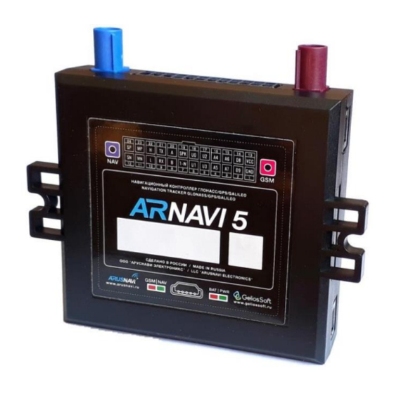
2. APPEARANCE OF THE DEVICE AND MAIN TRACKER CONNECTOR PINOUT The appearance of the device is presented in Fig. 1 and 2. The pin assignment of the main tracker connector is presented in Fig. 3 and described in Table 2. Fig. - Page 6 Fig. 3 – Main connector pinout Table 2 – Pin assignment of the main connector Design Intended purpose Application/connection ation Minus power Minus supply voltage Discrete Discrete / frequency / pulse sensors Analogue + Analogue sensors, discrete Analogue + Analogue sensors, discrete Output Switching current up to 540 mA Discrete...
-
Page 7: Tracker Setting
TRACKER SETTING 1.WEB CONFIGURATOR For the remote configuration of the tracker, a cloud service, web configurator, is used. It allows remotely configuring a device or group of devices without physical connection to the tracker via a cable or adapter. In addition, the web configurator service supports the function of the remote updating of device software. - Page 8 Step 3 – ‘Device data’ section displays general information: ID, IMEI, type, firmware version. Step 4 – ‘Server settings’ section. It is necessary to enter the address, port of the monitoring server, select the protocol type (INTERNAL or EGTS) and, if necessary, assign the server ID and password. Also, if necessary, you can assign a second address of the monitoring server.
- Page 9 Step 5 – For the efficient transmission of data to the server with consideration of traffic compression, select the dataset to be transmitted to the server in ‘Packet structure’ section. Note: In the simplest case of setting the device only for the purpose of determining the location of the mobile object (vehicle) without the use of inputs/outputs and other interfaces, it is enough to select only the first two points ‘Package structures’: GPS/GLONASS coordinates and GPS/GLONASS settings.
- Page 10 <If course change of – angle> – If the change of the angle between the routing of the last position sent to the server and the current routing exceeds the specified value, the current position will be sent to the server. Unit of measure: degree. <If speed change of –...
- Page 11 Step 8 – ‘Settings SIM card’ section The board has a holder for two SIM cards and two heat-resistant SIM chips. SIM card #1 (main) is installed in the upper compartment of the holder and SIM card #2 (backup) is installed in the lower compartment of the holder. The tracker initially establishes a connection via SIM card #1.
- Page 12 Step 9 – After entering the required settings, they should be saved. Go to ‘Device data’ section and click ‘Save settings’. Then, in the general table of devices, in ‘Status’ field, the ‘settings’ entry will appear. It shows that the device has been assigned new settings but they are not yet applied on the device. To apply the new settings, send a command to the device in one of the following ways: by SMS, a command from the server (see the description of commands in ‘SMS and TCP command list’...
- Page 13 To update the tracker software, you need to: 1. Select a device (check the box ‘device list’ on the left) 2. Open the ‘Set the firmware for the selected devices’ tab 3. Select the device type, firmware version and click ‘Apply’ Then, in the ‘Status’...
-
Page 14: Diagnostics Programm
2. DIAGNOSTICS PROGRAMM To check the correct operation and configuration of the tracker locally, you can use the ArnaviConfigurator programme, which allows providing a complete picture of the device as well as connected sensors and mechanisms at the installation site and configuring the tracker using the settings tree. - Page 15 To work with the programme, you will need to install the device driver, for which purpose: 4. Download the driver for the configurator from the website http://www.arusnavi.ru install it. 5. After completing the installation process, in the ‘STMicroelectronics’ folder, select and run the installation file"...
-
Page 16: Local Updating Of The Device Software
3. LOCAL UPDATING OF THE DEVICE SOFTWARE The device software can be updated in the main operation mode and in the bootloader mode. Updating of the device software in the main operation mode 1. Connect the device to a PC via USB. Once connected, the device will be identified as a removable media ‘APP’. -
Page 17: Setting Via Sms
4. SETTING VIA SMS The structure of the message with the command to change the settings is as follows: <access_password>*SETP*<changing_parameters_list> By default, the <access_password> field has the value123456. The <changing_parameters_list> field contains the number and value of one or more parameters to be changed. - Page 18 APN parameters of the SIM card’s mobile operator 1 – Parameter number:2 Command format: ‘#2=<name>,<user_name>,<password>’ Arguments: <name> – a string with a length of up to 32 symbols. Contains the name of the access point <user_name> – a string with a length of up 32 symbols. Contains the user name of the access point <password>...
- Page 19 when it is not necessary to change the speed. The value ‘0’ disables the condition of sending to the service by speed change. <interval> – a number within the range from 5 to 65535 or 0. If the interval between the time of the last sending of the coordinates to the server and the current time exceeds the specified value, the current position will be sent to the server.
- Page 20 Table 3 – Default device settings (factory settings) Parameter Description Default value number Monitoring hw.geliospro.ru,20144,0 server address APN parameters of the No parameters are specified; automatic mode SIM card’s mobile operator 1 400,18,20,150 (transmission of the point to the Trajectory processing server when passing a distance of 400 m, parameters changing the course by 18 degrees or changing...
-
Page 21: Guidelines For Connecting
GUIDELINES FOR CONNECTING The device is made in the form of a monoblock and requires a minimum number of connections for normal operation. The minimum set of actions required for the operation of the device is as follows: 1. Insert a SIM card(s) 2. -
Page 22: Discrete Inputs/Outputs
1. DISCRETE INPUTS/OUTPUTS The device has the following discrete inputs/outputs: four universal discrete inputs/outputs – IN0(U0), IN1(U1), IN2(U2), and IN3(U3); four analog inputs – IN4(A4), IN5(A5), IN6(A6), IN7(A7); two main discrete inputs – IN8(D8), IN9(D9). Each discrete input/output has several operation modes: Table 4 №... -
Page 23: Outputs
1.1 OUTPUTS The tracker supports control of four external executive devices that are connected to the universal contacts IN0(U0), IN1(U1), IN2(U2), and IN3(U3). Output type – open drain. In the active state, the outputs, including external devices, are ground- connected. The outputs allow for a load of up to 540 mA. - Page 24 ‘Output mode 1’ – the normal operation mode of the output with saving the state in non-volatile memory and recovery after restarting the device. The output status is changed by a command from the server or SMS. The output is forcibly deactivated when the operating mode is changed.
-
Page 25: Analog Inputs
1.2 ANALOG INPUTS The device has four analog inputs – IN4 (A4), IN5 (A5), IN6 (A6), and IN7 (A7), which support several operation modes for connecting the corresponding sensors. ‘Discrete mode’ shows the input state, when input voltage more than 6V – the input is activated (state “1”), else –... -
Page 26: Discrete Inputs
1.3 DISCRETE INPUTS The device has six discrete inputs: • two main discrete inputs – IN8 (D8) and IN9 (D9) • four universal discrete inputs/outputs – IN0 (U0), IN1 (U1), IN2 (U2), IN3 (U3). Discrete inputs have an internal pull-up to 3.3V. If input voltage less than 1V – state “1”, else – state “0”. - Page 27 Fig. 5 – Frequency FLSs connection diagram In the settings of the frequency FLS, specify the following parameters: • Output signal type – frequency • Frequency range: 30–4000 Hz • Activate the pull-up resistor When connecting frequency FLSs of other manufacturers, resistor pull-up may be required. The nominal value of the resistor is selected based on the on-board voltage and output parameters of the FLS.
-
Page 28: Digital Inputs
2. DIGITAL INPUTS The device has a set of digital interfaces for connecting external sensors as well as for the scalability of the device capabilities: RS232, RS485, 1-WIRE, CAN. Some digital interfaces have several operation modes: Table 5 № RS-232 RS-485 1-WIRE CAN EXT... -
Page 29: Rs-232 Interface
2.1 RS-232 INTERFACE For correct operation, it is necessary to set the respective operation mode of the R232 digital input in the tracker settings. “CAN EXT” mode – connecting an external CAN module via the RS232 interface. The programme number for CAN can be specified through the configurator in the field ‘CAN:’. - Page 30 In the section ‘Packet structure’ it is necessary to mark the necessary parameters to be transmitted to the server. “LLS 232” mode – connecting an FLS (Fuel Level Sensor) using RS232 interface supporting Omnicomm LLS protocol. Connecting an FLS using RS232 interface is similar to connecting an FLS using RS485 but has a number of specific features: •...
- Page 31 “MODBUS RTU” mode – connection of external devices via RS-232 interface supporting Modbus Protocol. Arnavi 5 works with Modbus Protocol only in data reading mode. Up to 20 registers (two or four-byte) can be read and transmitted to the server. If you need to transfer four-byte register, you must check the box ‘read 2 registers’...
- Page 32 If the external device has been configured and connected, then in the tab ‘COM port’ Arnavi Configurator at the time of reading will appear the rows with the values of the required registers: After reading the registers, a packet is generated and sent to the server: In Wialon system, read registers is contained in parameter “mbus_X”, X –...
- Page 33 Interval shooting. To activate, set the interval of photos from 1 to 65535 minutes. A value of 0 disables the interval shooting. Photo quality : 160×120, 320×240, 640×480. Connection: CAMERA SUPPLY VOLTAGE IS 5V. ARNAVI 5 CANNOT BE USED AS A POWER SOURCE FOR THE CAMERA. USER MANUAL [1.4] Page 33...
- Page 34 Interval shooting. To activate, set the interval of photos from 1 to 65535 minutes. A value of 0 disables the interval shooting. Photo quality : 160×120, 320×240, 640×480. Connection: CAMERA SUPPLY VOLTAGE IS 5V. ARNAVI 5 CANNOT BE USED AS A POWER SOURCE FOR THE CAMERA. USER MANUAL [1.4] Page 34...
- Page 35 Wi-Fi module has RS-232 interface and ‘EN’ input. If ‘EN’ is shorted to ground – module is activated. "EN" output can be rigidly closed to the ground, or can be connected to free arnavi 5 outputs (U0, U1, U2, U3). The last connection method allows the tracker to independently control the operation of the external module, as well as to reboot it in emergency situations.
- Page 36 In Arnavi-Configurator`s section "Common" displayed the current status of the WiFi module. Wi Fi module can have the following statuses: State Description Module not found Arnavi 5 cannot connect to module (it is necessary to check the connection and settings) Network searching Search for the access point specified in the settings Network connecting...
-
Page 37: Rs-485 Interface
2.2 RS-485 INTERFACE “CAN EXT” mode – connecting an external CAN module via the RS485 interface. The programme number for CAN can be specified through the configurator in the field ‘CAN:’. An external CAN module can also be connected in parallel with one or more FLS. To do this, you must select the mode "LLS | KUSS | PP-01". - Page 38 LLS | KUSS| PP-01 mode – work with fuel level sensors via RS485, signal pick-up device controller, and passenger traffic flow sensor PP-01. To control the flow as well as fuel filling and discharge operations, the device supports operation with external digital (RS-485 interface, 12 bit) fuel level sensors (capacitive, ultrasonic, etc.) that support Omnicomm’s LLS protocol.
- Page 39 Working with the signal pick-up device controller Data are transmitted from KUSS to the server in the form of two tags: KUSS_L Filling capacity in ml 156 0xNNTTTTTT KUSS_N, Filling operation number and filling operation duration KUSS_T ATTENTION: THE KUSS MODE COMBINED WITH LSS 485 MODE, WHICH ALLOWS SIMULTANEOUSLY USING BOTH FLSs AND KUSS AT THE BUS Working with the passenger traffic flow sensor PP-01 The tracker can simultaneously work with 4 passenger traffic flow sensors, which must have...
- Page 40 “MODBUS RTU” mode – connection of external devices via RS-485 interface supporting Modbus Protocol. Arnavi 5 works with Modbus Protocol only in data reading mode. Up to 20 registers (two or four-byte) can be read and transmitted to the server. If you need to transfer four-byte register, you must check the box ‘read 2 registers’...
- Page 41 If the external device has been configured and connected, then in the tab ‘COM port’ Arnavi Configurator at the time of reading will appear the rows with the values of the required registers: After reading the registers, a packet is generated and sent to the server: In Wialon system, read registers is contained in parameter “mbus_X”, X –...
- Page 42 Interval shooting. To activate, set the interval of photos from 1 to 65535 minutes. A value of 0 disables the interval shooting. Photo quality : 160×120, 320×240, 640×480. Connection: CAMERA SUPPLY VOLTAGE IS 5V. ARNAVI 5 CANNOT BE USED AS A POWER SOURCE FOR THE CAMERA. USER MANUAL [1.4] Page 42...
- Page 43 "Tachograph Shtrih" mode – allows you to connect the tachograph "Stroke" using RS-485 interface. Mode allows you to upload .DDD tachograph file to the server using SMS and TCP commands: SMS: <Access_password>*SERV*20.0 Upload data from tachograph "Shtrih" to server TCP: 2000 SMS: <...
-
Page 44: 1-Wire Interface
2.3 1-WIRE INTERFACE Connection of digital sensors via 1-WIRE interface To control the temperature of various devices or objects, temperature sensors are used. They operate via the 1-wire interface (up to 8 sensors can be connected simultaneously on one data bus). Also, in parallel with the temperature sensors it is possible to connect a connector for reading ibutton keys. - Page 45 When new temperature sensors are connected, they are automatically assigned id from 0 to 7, which they are transmitted to the server. In Wialon system, temperature sensor state is contained in parameter “Temp_1wire_X”, X – sensor number. ATTENTION: WHEN CONNECTING SENSORS USING A PARASITIC POWER SUPPLY (TWO-WIRE CONNECTION CIRCUIT), THE OPERATION OF UP TO 3 SENSORS ON THE BUS IS GUARANTEED.
-
Page 46: Can Interface
2.4 CAN INTERFACE Internal support of the CAN bus according to the standard J1939 Protocol, without using an external CAN module, is envisaged for the user’s convenience. The connection is made to pins 10 (L) and 22 (H) of the main connector of the device. The transmission rate is 250 kbps. -
Page 47: Connection Of The Speakerphone Communication With The Driver
3. CONNECTION OF THE SPEAKERPHONE COMMUNICATION WITH THE DRIVER The output volume of the device can be adjusted when the configuring the device. The connection diagram of the microphone and speaker is shown in Figure 9. Figure 9 – Diagram of connecting the microphone and speaker An external electret microphone with a balanced output should be used as a microphone for balanced connection. -
Page 48: Additional Functionality
ADDITIONAL FUNCTIONALITY 1. ROAMING – ADDITIONAL SETTINGS For any SIM can be enabled or disabled to work in roaming. In the roaming mode, will be active ‘Track settings in the roaming’. If any of the filters is not required (track settings in roaming, interval or buffer settings), then ‘0’ is entered in its field and it is disabled. -
Page 49: Indication Of Operation
INDICATION OF OPERATION To reflect the operation process, the tracker has two light indicators: NAV | GSM and PWR | BAT (Fig.10). Fig. 10 – Rear panel view (schematic) PWR | BAT light-emitting diode • Green light is on – external power is connected •... -
Page 50: Sms And Tcp Command List
SMS AND TCP COMMAND LIST The tracker supports receiving and processing SMS and TCP commands. The description of all available commands is presented in tables 6 - 8. Таблица 6 - SMS commands: Format Command description < access_password >*SETP* Command to configure the tracker. Detailed description of <parameter_list>... - Page 51 Table 5 TCP-commands from server Format Command description 0101 send a package with coordinates to the server immediately 0102 update the software via the web configurator even if assigned and current versions coincide 0105 update the software via the web configurator if assigned version differs from the current one 010550 update the software of the external CAN-module...
-
Page 52: Description Of Parameters In The Wialon System
DESCRIPTION OF PARAMETERS IN THE WIALON SYSTEM Prameter Parameter Description Comments Wialon Geliospro pwr_ext External power supply voltage pwr_int Internal battery voltage hdop hdop Horizontal Dilution of Precision cell_id GSM Base station unique ID GSM Location area code GSM Mobile network code GSM Mobile country code Range from 1 to 31 (99 –... - Page 53 Parameter Parameter Description Comments Wialon Geliospro can_eng_full_ CAN_FT CAN engine hours time can_full_ CAN_MLG CAN mileage mileage can_fuel_level_ CAN_FFC CAN fuel consumption cons can_fuel_level CAN_FLP CAN fuel level (%) can_fuel_level CAN_FFL CAN fuel level (liters) can_rpm CAN_RPM CAN engine rpm can_eng_temp CAN_T CAN engine temperature...
- Page 54 In the window that appears, fill in the required fields. In the ‘Message’ field, enter the command number and click ‘OK’ The created command will appear in the object properties. Save the object properties – click ‘OK’ USER MANUAL [1.4] Page 54...
-
Page 55: Warranty Obligations
WARRANTY OBLIGATIONS The equipment is designed for a long service life in the autonomous maintenance-free mode (except for the internal battery). The warranty period for the equipment is 5 years (except for the battery) and is counted from the moment of initial installation, provided it is carried out by the installer authorised by the manufacturer of the equipment. -
Page 56: Supply Package
The tracker is supplied in the configuration shown in Table 5. Table 5 – Tracker configuration Name Quantity Note Navigation controller Monitoring device ARNAVI 5 Main harness Comes with individual pins Backup battery (inside the tracker) Capacity depends on the modification GSM antenna 1–3 m (FAKRA) Navigation antenna 3–5 m (FAKRA)
Need help?
Do you have a question about the ARNAVI 5 and is the answer not in the manual?
Questions and answers