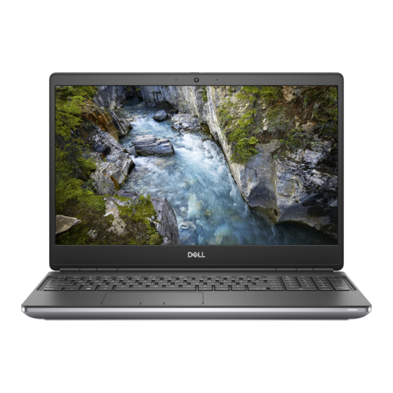
Dell Precision 7550 Service Manual
Hide thumbs
Also See for Precision 7550:
- Service manual (102 pages) ,
- Setup and specifications manual (45 pages) ,
- Connection manual (10 pages)

Related Manuals for Dell Precision 7550


Summary of Contents for Dell Precision 7550
- Page 1 Precision 7550 Service Manual Regulatory Model: P93F Regulatory Type: P93F001 May 2020 Rev. A00...
- Page 2 A WARNING indicates a potential for property damage, personal injury, or death. © 2020 Dell Inc. or its subsidiaries. All rights reserved. Dell, EMC, and other trademarks are trademarks of Dell Inc. or its subsidiaries. Other trademarks may be trademarks of their respective owners.
-
Page 3: Table Of Contents
Contents 1 Working on your computer......................6 Safety instructions.................................6 Before working inside your computer........................... 6 Safety precautions................................7 Electrostatic discharge—ESD protection........................7 ESD field service kit ................................8 After working inside your computer..........................8 2 Technology and components......................10 USB features..................................10 USB Type-C...................................11 HDMI 2.0.................................... - Page 4 WLAN card................................... 34 Removing the WLAN card............................34 Installing the WLAN card.............................. 35 WWAN card..................................36 Removing the WWAN card............................36 Installing the WWAN card............................36 Keyboard lattice................................... 37 Removing the keyboard lattice............................ 37 Installing the keyboard lattice............................38 Keyboard....................................38 Removing the keyboard..............................38 Installing the keyboard..............................
- Page 5 Display back cover................................95 Replacing the display cable............................95 4 Troubleshooting......................... 97 Dell SupportAssist Pre-boot System Performance Check diagnostics................97 Running the SupportAssist Pre-Boot System Performance Check............... 97 System board built-in self-test (M-BIST)........................98 Display panel power rail built-in self-test (L-BIST)......................98 Display panel built-in self-test (LCD-BIST)........................99...
-
Page 6: Working On Your Computer
Damage due to servicing that is not authorized by Dell is not covered by your warranty. Read and follow the safety instructions that came with the product. -
Page 7: Safety Precautions
Due to the increased density of semiconductors used in recent Dell products, the sensitivity to static damage is now higher than in previous Dell products. For this reason, some previously approved methods of handling parts are no longer applicable. -
Page 8: Esd Field Service Kit
It is recommended that all field service technicians use the traditional wired ESD grounding wrist strap and protective anti-static mat at all times when servicing Dell products. In addition, it is critical that technicians keep sensitive parts separate from all insulator parts while performing service and that they use anti-static bags for transporting sensitive components. - Page 9 CAUTION: To connect a network cable, first plug the cable into the network device and then plug it into the computer. 2. Connect your computer and all attached devices to their electrical outlets. 3. Turn on your computer. 4. If required, verify that the computer works correctly by running SupportAssist diagnostics. Working on your computer...
-
Page 10: Technology And Components
Technology and components This chapter details the technology and components available in the system. Topics: • USB features • USB Type-C • HDMI 2.0 • NVIDIA Quadro T1000 • NVIDIA Quadro T2000 • NVIDIA Quadro RTX3000 • NVIDIA Quadro RTX4000 •... -
Page 11: Usb Type-C
Speed Currently, there are five speed modes that are defined by the latest USB 3.0/USB 3.1 Gen 1 specification. Based on USB data transfer, they are categorized as Low Speed, Full Speed, High Speed (from version 2.0 of the specification), SuperSpeed (from version 3.0), and SuperSpeed+ (from version 3.1). - Page 12 it. A laptop might require up to 60 watts, for example. The USB Power Delivery specification ups this power delivery to 100 watts. It's bi- directional, so a device can either send or receive power. And this power can be transferred at the same time the device is transmitting data across the connection.
-
Page 13: Hdmi 2.0
NOTE: Data transfer speed may vary between different devices. Thunderbolt Icons Figure 2. Thunderbolt Iconography Variations HDMI 2.0 This topic explains the High-Definition Multimedia Interface (HDMI) 2.0 and its features along with the advantages. HDMI is an industry-supported, uncompressed, all-digital audio/video interface. HDMI provides an interface between any compatible digital audio/video source, such as a DVD player, or A/V receiver and a compatible digital audio and/or video monitor, such as a digital TV (DTV). -
Page 14: Nvidia Quadro T2000
Table 2. NVIDIA Quadro T1000(continued) Feature Values Memory bandwidth 128 Gbps Memory type GDDR6 Memory Interface 128-bit Clock Speeds 1395 - 1455 (Boost) MHz GPU base clock 8000 MHz (min. at P0) Estimated Maximum Power 50 W Display Support eDP/mDP/HDMI/Type-C Maximum Color Depth Up to 10 bit/color Operating Systems Graphics/ Video API Support... -
Page 15: Nvidia Quadro Rtx3000
NVIDIA Quadro RTX3000 Table 4. NVIDIA Quadro RTX3000 Feature Values Graphics memory 6 GB Cores 2304 Memory bandwidth 336 Gbps Memory type GDDR6 Memory Interface 192-bit Clock Speeds 945 - 1380 (Boost) MHz GPU base clock 3504 MHz (min. at P0) Estimated Maximum Power 80 W Display Support... -
Page 16: Nvidia Quadro Rtx5000
NVIDIA Quadro RTX5000 Table 6. NVIDIA Quadro RTX5000 Feature Values Graphics memory 16 GB Cores 3072 Memory bandwidth 448 Gbps Memory type GDDR6 Memory Interface 256-bit Clock Speeds 1035 / 1350 - 1545 / 1770 (Boost) MHz GPU base clock 14000 MHz Estimated Maximum Power 80 W... -
Page 17: Disassembly And Reassembly
Disassembly and reassembly SD card Removing SD card Prerequisites 1. Follow the procedure in before working inside your computer. About this task The figure indicates the location of the SD card and provides a visual representation of the removal procedure. Images to be uploaded in the next review cycle. -
Page 18: Installing Ssd Door
Steps 1. Push the SSD door towards left side to release the SSD door from the base cover. 2. Remove the SSD door from the base cover. Installing SSD door Prerequisites If you are replacing a component, remove the existing component before performing the installation procedure. About this task The figure indicates the location of the SSD door and provides a visual representation of the installation procedure. -
Page 19: Secondary M.2 Solid-State Drive
Steps 1. Place the SSD door into its slot on the base cover. 2. Push the SSD door towards right side to lock the SSD door. Next steps 1. Install the card. 2. Follow the procedure in after working inside your computer. -
Page 20: Installing The Secondary M.2 Ssd Module
Steps 1. Slide the SSD release latch to unlock the SSD module. 2. Remove the (M2x3) screw that secures the SSD module into its slot on the computer. 3. Remove the SSD module from the computer. 4. Remove the (M2x3) screw that secures the SSD thermal pad to the SSD carrier. 5. -
Page 21: Base Cover
Steps 1. For M.2 2280 SSD: a. Place the M.2 SSD onto its slot on SSD carrier. 2. For M.2 2230 SSD: a. Place the M.2 SSD into the SSD holder. b. Replace the (M2x2) screw to secure the M.2 SSD to the holder. c. - Page 22 Disassembly and reassembly...
- Page 23 Steps 1. Loosen the eight captive screws that secure the base cover to the computer. 2. Using a plastic scribe, pry open the base cover starting from bottom edge of the cover. NOTE: For models shipped without SmartCard reader, pry open the base cover from the smart card reader slot. Use your fingers to pry open the base cover as the use of plastic scribe or any other sharp objects may damage the base cover.
-
Page 24: Installing The Base Cover
3. Lift the base cover starting from the bottom edge and remove it from the computer. 4. Disconnect the battery cable from the connector on the system board. Installing the base cover Prerequisites If you are replacing a component, remove the existing component before performing the installation procedure. About this task The figure indicates the location of the base cover and provides a visual representation of the installation procedure. - Page 25 Disassembly and reassembly...
-
Page 26: Battery
If the battery gets stuck inside your computer as a result of swelling, do not try to release it as puncturing, bending, or crushing a lithium-ion battery can be dangerous. In such an instance, contact Dell technical support for assistance. See www.dell.com/contactdell. -
Page 27: Installing The Battery
Steps 1. Remove the three (M2x5) screws that secure the battery to the computer. 2. Slightly lift the battery and disconnect the battery cable from the connector on the battery. 3. Remove the battery away from the computer. Installing the battery Prerequisites If you are replacing a component, remove the existing component before performing the installation procedure. -
Page 28: Solid State Drive
Steps 1. Connect the battery cable to the connector in the battery. 2. Place the battery onto its slot in the computer. 3. Replace the three (M2x5) screws to secure the battery to the computer. Next steps 1. Install the base cover. - Page 29 Steps 1. Remove the (M2x3) screw that secures the SSD thermal plate to the M.2 SSD module. 2. Remove the SSD thermal plate. 3. For M.2 2280 SSD: a. Remove the (M2x3) screw that secures the M.2 SSD to the computer. b.
-
Page 30: Installing The Primary M.2 Ssd Module
Installing the primary M.2 SSD module Prerequisites NOTE: For computers shipped with M.2 2280 or 2230 SSD installed in slot 3 and/or slot 5. If you are replacing a component, remove the existing component before performing the installation procedure. About this task The figure indicates the location of the primary M.2 SSD and provides a visual representation of the installation procedure. -
Page 31: Secondary Memory Module
2. For M.2 2230 SSD: a. Place the M.2 SSD into the SSD holder. b. Replace the (M2x2) screw to secure the M.2 SSD to the holder. c. Place the M.2 SSD module onto its slot on the computer. d. Replace the (M2x3) screw to secure the M.2 SSD module to the computer. 3. -
Page 32: Installing The Secondary Memory Module
Installing the secondary memory module Prerequisites If you are replacing a component, remove the existing component before performing the installation procedure. About this task The figure indicates the location of the secondary and provides a visual representation of the installation procedure. Steps 1. -
Page 33: Installing The Sim Card
Steps 1. Gently slide the SIM card cover towards the left side of the system to unlock the SIM card cover. CAUTION: The SIM card cover is very fragile and can be easily damaged if it is not properly unlocked before opening. 2. -
Page 34: Wlan Card
Steps 1. Slide the SIM card into the SIM card slot. 2. Snap the SIM card cover down. 3. Slide the SIM card cover towards the right of the system to lock the cover. Next steps 1. Install the base cover. -
Page 35: Installing The Wlan Card
Steps 1. Loosen the captive screw that secures the WLAN card bracket to the system board. 2. Remove the WLAN card bracket away from the WLAN card. 3. Disconnect the antenna cables from the WLAN card. 4. Slide at an angle and remove the WLAN card from the connector on the system board. Installing the WLAN card Prerequisites If you are replacing a component, remove the existing component before performing the installation procedure. -
Page 36: Wwan Card
2. Install the card. 3. Follow the procedure in after working inside your computer. WWAN card Removing the WWAN card Prerequisites 1. Follow the procedure in before working inside your computer. 2. Remove the card. 3. Remove the base cover. About this task The figure indicates the location of the WWAN card and provides a visual representation of the removal procedure. -
Page 37: Keyboard Lattice
2. Connect the antenna cables to the connectors on the WWAN card. 3. Place the WWAN card bracket above the WWAN card to secure the antenna cables. 4. Tighten the (M2x3) screw to secure the WWAN card bracket to the system board. Next steps 1. -
Page 38: Installing The Keyboard Lattice
Installing the keyboard lattice Prerequisites If you are replacing a component, remove the existing component before performing the installation procedure. About this task The figure indicates the location of the M.2 SSD and provides a visual representation of the installation procedure. Steps 1. -
Page 39: Installing The Keyboard
About this task The figure indicates the location of the keyboard and provides a visual representation of the removal procedure. Steps 1. Lift the latch and disconnect the keyboard cable and the keyboard backlight cable from the connectors on the touchpad module. 2. - Page 40 Steps 1. Align the keyboard to its slot on the palmrest 2. Route the keyboard cable and the keyboard backlight cable through the bottom of the palmrest. 3. Replace the seven (M2x2) screws to secure the keyboard to the palmrest. 4.
-
Page 41: Primary Memory Module
Primary memory module Removing the primary memory module Prerequisites 1. Follow the procedure in before working inside your computer. 2. Remove the card. 3. Remove the base cover. 4. Remove the battery. 5. Remove the keyboard lattice. 6. Remove the keyboard. About this task The figure indicates the location of the primary memory module and provides a visual representation of the removal procedure. -
Page 42: Installing The Primary Memory Module
2. Lift the memory shield from the memory module to remove it from the computer. 3. Pry the securing clips from both side of the memory module until the memory module pops up. 4. Remove the memory module from the memory-module slot. NOTE: Repeat the above steps if there are other memory installed. -
Page 43: Heat Sink
4. Place the memory shield above the memory module. 5. Replace the (M2x3) screw to secure the memory shield to the memory module. Next steps 1. Install the keyboard. 2. Install the keyboard lattice. 3. Install the battery. 4. Install the base cover. -
Page 44: Installing The Heat Sink Assembly
4. Lift the heat-sink assembly to remove it from the computer. Installing the heat sink assembly Prerequisites If you are replacing a component, remove the existing component before performing the installation procedure. About this task The figure indicates the location of the keyboard and provides a visual representation of the installation procedure. Steps 1. -
Page 45: Power-Adapter Port
Power-adapter port Removing the power-adapter port Prerequisites 1. Follow the procedure in before working inside your computer. 2. Remove the card. 3. Remove the base cover. 4. Remove the battery. 5. Remove the heat-sink assembly. About this task The figure indicates the location of the power-adapter port and provides a visual representation of the removal procedure. Steps 1. -
Page 46: Power Button Board
Steps 1. Align and place the power-adapter cable on the computer. 2. Place the power-adapter port into its slot on the plamrest. 3. Replace the power-adapter cable bracket on the power-adapter port. 4. Replace the (M2x3) screw to secure the power-adapter cable bracket to the computer. 5. -
Page 47: Installing The Power Button Board
Steps 1. Disconnect the power button board cable from the connector on the system board. 2. Peel the power button board cable from the palmrest. 3. Remove the (M2x3) screw that secures the power button board to the computer. 4. Remove the power button board with the power button board cable from the computer. 5. -
Page 48: Power Button Board With Fingerprint Reader
Steps 1. Connect the power button board cable to the power button board. 2. Align and place the power button board with power button cable into its slot on the computer. 3. Replace the (M2x3) screw to secure the power button board. 4. -
Page 49: Installing The Power Button Assembly With Fingerprint Reader
Steps 1. Remove the (M2.5x2.5) screw that secures the power button assembly with fingerprint reader cable bracket to the power button board. 2. Remove the power button assembly with fingerprint reader cable bracket from the power button board. 3. Disconnect the power button assembly with fingerprint reader cable from the power button board. 4. -
Page 50: Installing The Inner Frame
About this task The figure indicates the location of the inner frame and provides a visual representation of the removal procedure. Steps 1. Unroute the WLAN and WWAN antenna cables from the routing guide. 2. Remove the eight (M2x5) and the ten (M2x2.5) screws that secure the inner frame to the computer chassis. 3. -
Page 51: Smart Card Cage
Steps 1. Align and place the inner frame in the computer chassis. 2. Replace the eight (M2x5) and the ten (M2x2.5) screws to secure the inner frame in place. 3. Route the WLAN and WWAN antenna cables through the routing guide. Next steps 1. -
Page 52: Installing The Smart-Card Reader
About this task The figure indicates the location of the smart-card reader and provides a visual representation of the removal procedure. Steps 1. Disconnect the touchpad buttons cable from the touchpad. 2. Disconnect the smart-card reader cable from the connector on the USH daughter board. 3. -
Page 53: Touchpad Button
Steps 1. Align and place the smart-card reader into its slot on the computer. 2. Replace the two (M2x2.5) screws to secure the smart-card reader in place. 3. Adhere the smart-card reader cable to the touchpad. 4. Connect the smart-card reader cable to the connector on the USH daughter board. 5. -
Page 54: Installing The Touchpad Buttons
Steps 1. Disconnect the touchpad buttons cable from the connector on the touchpad. 2. Remove the two (M2x2.5) screws that secure the touchpad buttons to the palmrest. 3. Remove the touchpad buttons from the palmrest. Installing the Touchpad buttons Prerequisites If you are replacing a component, remove the existing component before performing the installation procedure. -
Page 55: Sd Card Reader
Steps 1. Place the touchpad buttons into its slot in the palmrest. 2. Replace the two (M2x2.5) screws to secure the touchpad buttons to the palmrest 3. Connect the touchpad buttons cable to the connector in the touchpad. Next steps 1. -
Page 56: Installing Sd Card Reader
2. Disconnect the LED board cable from the SD card reader on the bottom side of the computer. 3. Remove the (M2x2) screw that secures the SD card reader in place. 4. Slide and remove the SD card reader with its cable out of the computer. Installing SD card reader Prerequisites If you are replacing a component, remove the existing component before performing the installation procedure. -
Page 57: Power Button
Power button Removing the power button Prerequisites 1. Follow the procedure in before working inside your computer. 2. Remove the card. 3. Remove the base cover. 4. Remove the battery. 5. Remove the heat-sink assembly. 6. Remove the power button board. -
Page 58: Power Button Assembly With Fingerprint Reader
Steps 1. Place the power button into its slot on the computer. 2. Replace the two (M2x3) screws to secure the power button in place. Next steps 1. Install the power button board. 2. Install the heat-sink assembly. 3. Install the battery. 4. -
Page 59: Installing The Power Button Assembly With Fingerprint Reader
Steps 1. Remove the two (M2x3) screws that secure the power button assembly with fingerprint reader in its slot on the computer. 2. Remove the power button assembly with fingerprint reader from the computer. Installing the power button assembly with fingerprint reader Prerequisites If you are replacing a component, remove the existing component before performing the installation procedure. -
Page 60: Gpu Power Cable
Steps 1. Place the power button assembly with fingerprint reader into its slot on the computer. 2. Replace the two (M2x3) screws to secure the power button assembly with fingerprint reader in place. Next steps 1. Install the power button board assembly with fingerprint reader. -
Page 61: Installing The Gpu Power Cable
2. Slightly slide the GPU power cable connector outwards to disconnect the GPU power cable from the GPU card. 3. Repeat the above steps to disconnect the GPU power cable from the system board. 4. Peel the GPU power cable from the computer. Installing the GPU power cable Prerequisites If you are replacing a component, remove the existing component before performing the installation procedure. -
Page 62: System Board
System board Removing the system board Prerequisites 1. Follow the procedure in before working inside your computer. 2. Remove the card. 3. Remove the door. 4. Remove the secondary M.2 SSD. 5. Remove the base cover. 6. Remove the battery. 7. - Page 63 Steps 1. Carefully pry the GPU power cable connector outside the end of the connector head to unlock the GPU power cable connector from the system board on top side of the system. 2. Slightly slide the GPU power cable connector outwards to disconnect the GPU power cable from the connector on the system board. 3.
-
Page 64: Installing The System Board
NOTE: For UMA models, remove the two (M2x3) screws that secure the single beam connector in place on the bottom of the system. 10. Remove the beam connectors from the computer. 11. Remove the (M2x5) screw that secures the display cable bracket in place. 12. - Page 65 Disassembly and reassembly...
- Page 66 Steps 1. Adhere the coin-cell battery to the palmrest and then place the system board on its slot on the palmrest. 2. Replace the three (M2x5) screws to secure the system board to the palmrest. 3. Connect the display cable, touch screen cable (for models shipped with a touch screen) or IR camera cable (for models shipped with an IR camera), power adapter cable, touchpad cable, USH daughter board FFC (for models shipped with a USH daughter board), and power button board cable to the connectors on the system board.
-
Page 67: Gpu Card
4. Install the keyboard. 5. Install the keyboard lattice. 6. Install the WLAN card. 7. Install the WWAN card. 8. Install the secondary memory. 9. Install the card. 10. Install the primary M.2 SSD. 11. Install the inner frame. 12. Install the battery. 13. -
Page 68: Installing The Gpu Card
Installing the GPU card Prerequisites If you are replacing a component, remove the existing component before performing the installation procedure. About this task The figure indicates the location of the GPU card and provides a visual representation of the installation procedure. Images to be uploaded in the next review cycle Steps 1. -
Page 69: Installing The Speaker
14. Remove the primary memory. 15. Remove the heat-sink assembly. 16. Remove the inner frame. 17. Remove the GPU power cable. 18. Remove the card. 19. Remove the system board. About this task The figure indicates the location of the speaker and provides a visual representation of the removal procedure. Images to be uploaded in the next review cycle. - Page 70 Steps 1. Align and place the speaker module into its slot on the top edge of the palmrest. 2. Adhere the three piece adhesive tape to secure the speaker cable in place on the palmrest. Next steps 1. Install the system board.
-
Page 71: Middle Cap
Middle cap Removing the middle cap Prerequisites 1. Follow the procedure in before working inside your computer. 2. Remove the card. 3. Remove the door. 4. Remove the secondary M.2 SSD. 5. Remove the base cover. 6. Remove the battery. 7. -
Page 72: Installing The Middle Cap
2. Remove the middle cap from the computer. Installing the middle cap Prerequisites If you are replacing a component, remove the existing component before performing the installation procedure. About this task The figure indicates the location of the middle cap and provides a visual representation of the installation procedure. Steps 1. -
Page 73: Display Assembly
15. Install the base cover. 16. Install the secondary M.2 SSD. 17. Install the door. 18. Install the card. 19. Follow the procedure in after working inside your computer. Display assembly Removing the display assembly Prerequisites 1. Follow the procedure in before working inside your computer. - Page 74 Disassembly and reassembly...
-
Page 75: Installing The Display Assembly
8. Remove the display assembly from the palmrest. NOTE: The touch display assembly for Precision 7550 is a Hinge-Up Design (HUD) assembly and cannot be further disassembled once it is removed from the bottom chassis. If any components in the touch display assembly are malfunctioning and need to be replaced, replace the entire touch display assembly. - Page 76 Disassembly and reassembly...
- Page 77 Steps NOTE: Before installing the display assembly, ensure that the display hinges are opened to a 140-degree angle against the display assembly, to fit the display assembly to the palmrest. Align the screw holes on the hinges on the display assembly to the screw holes on the palmrest. 2.
-
Page 78: Palm Rest
12. Install the secondary M.2 SSD. 13. Install the door. 14. Install the card. 15. Follow the procedure in after working inside your computer. Palm rest Removing the palmrest Prerequisites 1. Follow the procedure in before working inside your computer. 2. -
Page 79: Installing The Palmrest
Installing the palmrest Prerequisites If you are replacing a component, remove the existing component before performing the installation procedure. About this task The figure indicates the palmrest and before performing the pre-installation parts procedures for any palmrest installation procedure. Next steps 1. -
Page 80: Display Bezel
2. Install the middle cap. 3. Install the speaker. 4. Install the system board. 5. Install the card. 6. Install the GPU power cable. 7. Install the inner frame. 8. Install the heat-sink assembly. 9. Install the power button power button assembly with fingerprint reader. -
Page 81: Installing The Display Bezel (Non-Touch)
22. Remove the display assembly. About this task The figure indicates the location of the display bezel and provides a visual representation of the removal procedure. Images to be uploaded in the next review cycle. Steps 1. Using a flat head tool or a plastic scribe, pry open the display bezel from the two recess points on the bottom edge of the display bezel. - Page 82 Steps 1. Place the display bezel on the display assembly. 2. Press the edges of the display bezel until it clicks onto the display assembly. Next steps 1. Install the display assembly. 2. Install the middle cap. 3. Install the speaker. 4.
-
Page 83: Display Panel
21. Install the card. 22. Follow the procedure in after working inside your computer. Display panel Removing the display panel (non-touch) Prerequisites 1. Follow the procedure in before working inside your computer. 2. Remove the card. 3. Remove the door. 4. - Page 84 Steps 1. Remove the two (M2.5x2.5) screws and the two (M2x2.5) screws that secures the display panel to the display assembly. 2. Lift the display panel and turn the display panel over to access the display cable 3. Peel the conductive tape covering the display cable. 4.
-
Page 85: Installing The Display Panel (Non-Touch)
Installing the display panel (non-touch) Prerequisites If you are replacing a component, remove the existing component before performing the installation procedure. About this task The figure indicates the display panel and provides a visual representation of the installation procedure. Steps 1. -
Page 86: Display Hinges
5. Replace the two (M2.5X2.5) and two (M2x2.5) screws to secure the display panel to the display assembly. Next steps 1. Install the display bezel. 2. Install the display assembly. 3. Install the middle cap. 4. Install the speaker. 5. Install the display assembly. -
Page 87: Installing The Display Hinge (Non-Touch)
22. Remove the display bezel. 23. Remove the display panel. About this task The figure indicates the location of the display hinge and provides a visual representation of the removal procedure. Images to be uploaded in the next review cycle. Steps 1. - Page 88 Steps 1. Place the display hinge in its slot on the display assembly. 2. Replace the eight (M2.5x2.5) screws to secure the display hinge to the display assembly. Next steps 1. Install the display panel. 2. Install the display bezel. 3.
-
Page 89: Camera
Camera Removing the camera (non-touch) Prerequisites 1. Follow the procedure in before working inside your computer. 2. Remove the card. 3. Remove the door. 4. Remove the secondary M.2 SSD. 5. Remove the base cover. 6. Remove the battery. 7. Remove the primary M.2 SSD. -
Page 90: Installing The Camera
Steps 1. Peel the adhesive tape that covers the camera module. 2. Disconnect the display cable from the camera module. 3. Gently pry the camera shutter cap from the top edge of the camera shutter and remove it from the display back cover. 4. -
Page 91: P-Sensor Board
13. Install the WLAN card. 14. Install the WWAN card. 15. Install the secondary memory. 16. Install the card. 17. Install the primary M.2 SSD. 18. Install the battery. 19. Install the base cover. 20. Install the secondary M.2 SSD. 21. -
Page 92: Installing The P-Sensor Board
Installing the P-sensor board Prerequisites If you are replacing a component, remove the existing component before performing the installation procedure. About this task The figure indicates the P-sensor board and provides a visual representation of the installation procedure. Images to be uploaded in the next review cycle Steps 1. - Page 93 9. Remove the secondary memory. 10. Remove the WWAN card. 11. Remove the WLAN card. 12. Remove the keyboard lattice. 13. Remove the keyboard. 14. Remove the primary memory. 15. Remove the heat-sink assembly. 16. Remove the inner frame. 17. Remove the GPU power cable.
-
Page 94: Installing The Display Cable
4. Remove the display cable from the display back cover. Installing the display cable Prerequisites If you are replacing a component, remove the existing component before performing the installation procedure. About this task The figure indicates the display cable and provides a visual representation of the installation procedure. Steps 1. -
Page 95: Display Back Cover
8. Install the GPU power cable. 9. Install the inner frame. 10. Install the heat-sink assembly. 11. Install the primary memory. 12. Install the keyboard. 13. Install the keyboard lattice. 14. Install the WLAN card. 15. Install the WWAN card. 16. - Page 96 For installing the components, place the display back cover on a flat surface. 1. Install the display cable. 2. Install the camera. 3. Install the display hinges. 4. Install the P-sensor board. 5. Install the display panel. 6. Install the display bezel.
-
Page 97: Troubleshooting
About this task The SupportAssist diagnostics (also known as system diagnostics) performs a complete check of your hardware. The Dell SupportAssist Pre-boot System Performance Check diagnostics is embedded with the BIOS and is launched by the BIOS internally. The embedded system diagnostics provides a set of options for particular devices or device groups allowing you to: •... -
Page 98: System Board Built-In Self-Test (M-Bist)
System board built-in self-test (M-BIST) About this task Steps 1. Press and hold both the M key and the power button to initiate M-BIST. 2. The battery-status light illuminates in amber when there is a system board failure. 3. Replace the system board to fix the issue. NOTE: The battery status LED does not illuminate if the system board is functioning properly. -
Page 99: Display Panel Built-In Self-Test (Lcd-Bist)
Display panel built-in self-test (LCD-BIST) About this task Steps 1. Press and hold the D key, and then press the power button. 2. Release both the D key and the power button when the computer begins POST. 3. The display panel begins to display a solid color, or cycling through different colors. NOTE: The sequence of colors may vary depending on the different display panel vendors. -
Page 100: Wifi Power Cycle
Table 7. LED codes(continued) Diagnostic light codes Problem description Recommended Solution Unrecoverable SPI Flash Failure Replace System Board 1, 5 EC unable to program i-Fuse Replace System Board 1, 6 Generic catch-all for ungraceful EC code flow Disconnect all power source (AC, battery, coin cell) and errors drain flea power by pressing &... - Page 101 NOTE: Some ISPs (Internet Service Providers) provide a modem/router combo device. Steps 1. Turn off your computer. 2. Turn off the modem. 3. Turn off the wireless router. 4. Wait for 30 seconds. 5. Turn on the wireless router. 6. Turn on the modem. 7.
-
Page 102: Getting Help
About this task Dell provides several online and telephone-based support and service options. Availability varies by country and product, and some services may not be available in your area. To contact Dell for sales, technical support, or customer service issues: Steps 1.
Need help?
Do you have a question about the Precision 7550 and is the answer not in the manual?
Questions and answers