Table of Contents
Advertisement
Quick Links
※Specifimations may be changed without notice.
HEAD OFFICE&FACTORY :700 Shimohinata, K anuma-shi, Tochigi-ken 322-8666, Japan
TE L:0289-64-3380
TOKYO OFFICE:6F MY Bldg., 1-13-3 Ueno, Taito-ku, Tokyo 110-0005, Japan
TE L :03-3835-2892
http://www.nsk-nakanishi.co.jp e-mail: box@nsk-nakanishi.co.jp
NSK AMERICA CORPORATION
700 B Cooper Court
Schaumburg, Illinois 60173
Tel. ( 847) 843-7664 Fax. ( 847) 843-7622
FAX:0289-62-5636
FAX :03-3835-2856
ASTRO-E 400 / 500 SYSTEM
OPERATION MANUAL
P.1-2 INSTRUCTIONS AND WARNINGS
P.3-4 SPECIFICATIONS
P.5
INSTRUCTIONS FOR SWITCHING VOLTAGE
P.6
CONNECTION OF MOTOR CORD AND
POWER CORD
P.7
P.8
MOUNTING BRACKET
'04.04.005.◯ A
CONTENTS
P.9-10 OPERATION PROCEDURES
P.11
P.12
SYSTEM CHART
P.13
P.14
OM-K0054E
Rev.3
Advertisement
Table of Contents

Related Manuals for NSK Nakanishi ASTRO-E 400


Summary of Contents for NSK Nakanishi ASTRO-E 400
- Page 1 TOKYO OFFICE:6F MY Bldg., 1-13-3 Ueno, Taito-ku, Tokyo 110-0005, Japan MOUNTING BRACKET TE L :03-3835-2892 FAX :03-3835-2856 OPERATION PROCEDURES http://www.nsk-nakanishi.co.jp e-mail: box@nsk-nakanishi.co.jp NSK AMERICA CORPORATION 700 B Cooper Court Schaumburg, Illinois 60173 Tel. ( 847) 843-7664 Fax. ( 847) 843-7622...
- Page 2 B. OTHER WARNING INSTRUCTIONS IMPORTANT INSTRUCTIONS AND WARNING - Electric Devices 1. For your own safety read instruction manual before operating tool. 2. Wear eye protection. WARNING ! 3. Replace cracked wheel immediately. When using electric tools, basic safety precautions should always be followed to reduce the risk of fire, electrical shock and personal injury, including the following.
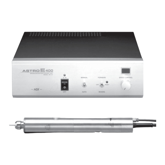
- Page 3 ◆SPECIFICATION PRODUCT ASTRO-E 400 ASTRO-E 500 MODEL NE52 NE52-500 POWER SOURCE 115/230VAC Switchable 50-60Hz 115/230VAC Switchable 50-60Hz POWER CONSUMPTION 170W 170W 5.5kg (12.1 lbs) 5.5kg (12.1 lbs) WEIGHT W301×D262×H97 A DIMENSION W301×D262×H97 A EMS-3041, EM-401, EM-501, EMS-3045, EMS-3052, !3 S equence Control Joint MOTOR MODEL EM-405, EM-505, EMS-3040A, !4 I nlet with Power Fuse EMS-3056, EM-401A EMS-3051, EM-501A !6 V oltage Switching Terminal 115/230V EMS-3052A EMS-3055,...
- Page 4 ◆INSTRUCTION FOR SWITCHING VOLTAGE ◆CONNECTING MOTOR CORD AND POWER CORD Connect the motor cord to Connector for Motor Cord !1 and fasten with the cord nut. (Fig. 7) WARNING This device can be used on either 115 V or 230 V. Be sure to follow the Plug the power cord for 115 V or 230 V in Inlet with Power Fuse !4 . instruction below for switching voltage, because using with the voltage other than 115 V and 230 V may cause malfunction, electric shock and fire. ●How to use Voltage Switching Terminal !6 ( Power Supply Voltage) A) 115V INPUT (110 V - 120 V) Connect upper and bottom two terminals marked 115 V by connecting plates respectively. (See Fig. 5.) Connecting plates Fig. 7 115V Voltage Switching Terminal ◆CONNECTION OF AIR HOSE 230V ¡ Connect a φ4.0 air hose from the motor to Motor Cooling Joint !0 at the back of the control unit by using a φ6/φ4 adaptor. ...
- Page 5 ◆MOUNTING BRACKET ( FOR RACK MOUNT ) ◆SEQUENCE CONTROL CONNECTION Remove 4 screws from each side of left and right on the control unit and fix the bracket on ・Speed between 0-40,000 min (ASTRO-E 400) the control unit as shown on Fig.11. or 0-50,000 min (ASTRO-E 500) can be controlled variably when an external voltage Fig. 11 (0-10 VDC,1 mA Max.) is connected to the SPEED terminal. (Fig.9) ・Motor runs in the reverse direction when 24 VDC is applied between the R/L and COM Ω terminals, and in the forward direction when SPEED ˜ Screw Bracket 3KΩ 0 VDC is applied. (Fig.9) DC24V 510Ω Bracket ・Motor starts to run when 24 VDC is applied DC24V 510Ω ON/OFF between ON/OFF and COM terminals, and 3KΩ ...
- Page 6 Operation‐2 Automatic Operation (See Fig. 11) ◆CONNECTING SPINDLE TO MOTOR a Turn Power Switch i ON. (Green Lamp u lights.) Align the threads on the front end of the motor and the rear of the spindle, and turn the s Select MANUAL/AUTO Selector Switch y to AUTO side. spindle clockwise. If the drive shaft of the motor does not engage the drive dog on the ¡ Operate under the external control equipment(sequence control ) .See P7 Connecting spindle, you may only be able to turn it about 2 turns. DO NOT FORCE. Turn the spindle back a few threads, rotate the spindle by hand to engage the drive shaft and the drive dog, Sequence Control Terminal !3 for connection. and screw them together. ¡ When Speed Control Selector Switch o is on EXT side, the motor speed and switching FWD/REV can be controlled under Sequence Control.
- Page 7 ◆ASTRO-E 400 / 500 SYSTEM CHART ◆REPLACING COLLET CHUCK a Loosen and remove the collet cap with cutting tool according to the "Replacing Cutting Tool" steps above. s Remove the cutting tool from the collet chuck. d To remove the collet chuck from the collet cap, hold the collet cap in one hand and incline Collet Cap K-265 the collet chuck toward the spanner slit of the collet cap. Motor Spindle Motor Spindle (Cord with intermediate connector) EMS-3041 ・ EMS-3051 EMS-3045 ・ EMS-3055 Collet Chuck CHK-□□ f To mount a new collet chuck, incline the collet chuck toward the spanner slit of the collet EMS-3052 EMS-3056 cap and insert. Axis for Drill Chuck DCH-J0K (Jacob's taper No.0) Spindle NR-402E ・ NR-452E Air Line Kit Tool AL-0201 Collet Cap Axis for Metal Saw KCH-03 Spanner Slit...
- Page 8 ◆ACCESSORIES ◆TROUBLESHOOTING Check the following table for any abnormalities. If problem persists, please contact your local distributor for service. ■ Collet Chucks List 〈Control Unit NE52, NE52-500 and Motor〉 Product Model Size of Inside Diameter d (mm) Fit to Trou- Check Point Cause Countermeasure 23.5 d I.D.= d φ2.35,φ3.0,φ3.175 RA-270E CHS-□□ φ0.8-φ2.9 every 0.1A Power cord is unplugged. Connect power plug. 34.4 d I.D.= d NR-410E ATC Power Lamp does not light φ2.0,φ3.0,φ3.175 Blow out of fuse. Change fuses. (Page 9) CHP-□□ NR-420E ATC when power switch is ON. System will automatically turn on 34.4 d ...
Need help?
Do you have a question about the Nakanishi ASTRO-E 400 and is the answer not in the manual?
Questions and answers