Table of Contents
Advertisement
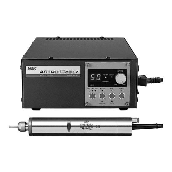
ASTRO-E 400Z/500Z/800Z SYSTEM
OPERATION MANUAL
2.Features.......................................4
3.Specifications..............................4
4.Torque/Output Characteristics.........5
5.Nomenclature..............................6
6.Diagrams....................................8
8.Changing Fuses ...........................9
9.Power Cord Connection..................9
10.Motor Cord Connection ..................10
11.Air Hose Connection.....................10
contents
Devices...1
13.Changing Tools ...........................11
14.Replacing the Collet........................12
15.Fixturing the Motor and Spindle.........12
16.Operation Procedures.....................13
18.Protect Function...........................20
19.Break-In Procedure........................21
20.Cutting tool cautions.....................22
21.Optional Parts..............................23
22.Trouble Shooting...........................25
OM-K0356E Rev.1
Advertisement
Table of Contents

Related Manuals for NSK ASTRO-E 400Z


Summary of Contents for NSK ASTRO-E 400Z
-
Page 1: Table Of Contents
ASTRO-E 400Z/500Z/800Z SYSTEM OPERATION MANUAL OM-K0356E Rev.1 contents 12.Connecting the Motor and Spindle…11 INSTRUCTIONS AND WARNING-Electric Devices…1 13.Changing Tools ………………………11 1.Cautions for handling and operation…2 14.Replacing the Collet……………………12 2.Features…………………………………4 15.Fixturing the Motor and Spindle………12 3.Specifications…………………………4 16.Operation Procedures…………………13 4.Torque/Output Characteristics………5 17.External Input/Output Control Signal Specifications…15 5.Nomenclature…………………………6 18.Protect Function………………………20 6.Diagrams………………………………8 19.Break-In Procedure……………………21 7.Input Voltage Switching (115V-230V)…8 20.Cutting tool cautions…………………22 8.Changing Fuses ………………………9 21.Optional Parts…………………………23 9.Power Cord Connection………………9 10.Motor Cord Connection ………………10 22.Trouble ... -
Page 2: Instructions And Warning-Electric Devices
IMPORTANT INSTRUCTIONS AND WARNING - Electric Devices WARNING! When using electric tools, basic safety precautions should always be followed to reduce the risk of fire, electrical shock and personal injury, including the following. Read all these instructions before operating this product and save these instructions. GROUNDING INSTRUCTIONS 1. In the event of a malfunction or breakdown, grounding provides a path of least resistance for electric current to reduce the risk of electric shock. This tool is equipped with an electric cord with a grounding conductor and a grounding plug. The plug must be plugged into a matching outlet that is properly installed and grounded in accordance with all local codes and ordnances. 2. Don't modify the plug provided - if it will not fit the outlet, have the proper outlet installed by a qualified electrician. 3. Improper connection of the grounding conductor can result in electric shock. The conductor with insulation having an outer surface that is green with or without yellow stripes is the grounding conductor. If repair or replacement of the electric cord or plug is necessary, do not connect the grounding conductor to a live terminal. 4. Check with a qualified electrician or service person if the grounding instructions are not completely understood, or if in doubt as to whether the tool is properly grounded. 5. Use only 3-wire extension cords that have 3-prong grounding plugs and 3-pole receptacles that accept the tool's plug. 6. Repair or replace damaged or worn cord immediately. 7. This tool is intended for use on a circuit that has an outlet that looks like the one illustrated in Sketch A in Figure (below)(115V). The tool has a grounding plug that looks like the plug illustrated in Sketch A in Figure (below). A temporary adapter, which looks like the adapter illustrated in Sketches B and C, may be used to connect this plug to a 2-pole receptacles as shown in Sketch B if a properly grounded outlet is not available. The temporary adapter should be used only until a properly grounded outlet can be installed by a qualified electrician. The green-colored rigid ear, lug, and the like, extending from the adapter must be connected to a permanent ground such as a properly grounded outlet box. Grounding Method ADAPTER METAL SCREW GROUNDING COVER OF GROUND (C) MEANS GROUNDING OUTLET BOX PIN GROUNDING ... -
Page 3: 1.Cautions For Handling And Operation
Thank you for purchasing the Ultra-Precision, High-Speed spindle system, ASTRO-E 400Z/500Z/800Z. ASTRO-E400Z/500Z/800Z System is designed for use on CNC lathes, robots, NC lathes and special purpose machines. The motor, spindle and control unit are designed to work as an integrated system capable of 0-40,000min (400Z) ,0-50,000 (500Z),0-80,000min (800Z). - Page 4 ! CAUTION ①DO NOT block the cooling vent on the back of ASTRO-E400Z/500Z/800Z control unit. Blocking the air vents will greatly increase heat buildup in the control unit and cause damage to the internal components of the control unit. ②When using tools at motor speeds of less than 2,000min (rpm), the appropriate speed reducer(For ASTRO-E400Z/500Z)needs to be attached.
- Page 5 Features 2 A high-speed brushless motor is used to achieve extremely high speed and eliminate the nuisance of ① brush maintenance. Motor speed is digitally displayed. ② Wide motor speed range: 0-40,000min (400Z ) ,0-50,000min (500Z ) and 0-80,000min (800Z). ③...
- Page 6 Spindle ③ Model ASTRO-E400Z ASTRO-E500Z ASTRO-E800Z NR-402E EMS-3041 NR-452E EMS-3052 Spindle Type NRA-5080 EMS-3056 NR-3080 EMS-3045 EM-401 EM-501 EM-801 Adoptable Motor EM-405 EM-505 EM-805 Allowed motor speed 40,000min 50,000min 80,000min Spindle Accuracy Within 1 μ HES500 ④ ASTRO-E500Z Model HES500-BT30/NT30 HES500-BT40/NT40 ...
- Page 7 Nomenclature 5 ①Input/Output Connector CN1 ②Input/Output Connector CN2 ③Motor Connector ④Cooling Air Output Joint ⑤Power Supply Voltage Selector Switch ⑥Air Input Joint ⑦Main Power Inlet with Fuse Holder Fig.1 ⑧Power Switch Control unit (Fig.1) ( ) ①Input/Output Connector CN1 ⑥Air Input Joint This is the connector for automatic control Supply clean, dry, regulated air for motor and monitoring of the control unit's safety cooling. The air supply needs to be regulated systems. ...
- Page 8 Control Panel (Fig.2) ( ) B Power Lamp ⑬Speed Adjustment Knob G Auto Lamp A Error Lamp ⑭Digital Speed Indicator(Speed) K Load Monitor Lamp (LOAD) C Motor Lamp J Internal Lamp I External Lamp D FWD. Lamp H 500 Lamp ⑨Start Switch ⑫Motor Speed Selection Switch F Manual Lamp ⑩Forward/Reverse Switch E REV.Lamp ⑪Controller Switch(AUTOーMANUAL) Fig.2 ⑨Start Switch Starts and stops motor rotation ⑭Digital Speed Indicator (SPEED) ⑩Forward/ Reverse Switch Preset Speed, Actual Speed, Warning and Error This switch controls the direction of rotation, Codes are displayed to 2 digits. forward (FWD) or reverse (REV). With the cutting Error Lamp:When an error exists this lamp lights tool facing the operator right hand rotation (FWD) and the error code is shown on the digital display. will be clockwise rotation. Power Lamp:Power Switch is in the ON position. ⑪Controller Switch (AUTOーMANUAL) Motor Lamp:Motor is rotating (except at the This switch selects motor/spindle control from the minimum of speed adjustment knob) ...
-
Page 9: 7.Input Voltage Switching (115V-230V)
Diagrams 6 (1) Motor/Spindle Diagram(Example) (17.4) (17.4) Fig.3 (2) Control Unit Diagram (ASTRO-E400Z/500Z/800Z are the same) CN1 CN2 AIR OUT SPEED −1 MAX 50,000min Model NE147 POWER ERROR MOTOR −1 x1000min MIN MAX ON LOAD INT EXT 500 AUTO FWD START VOLTAGE OFF AIR IN ... -
Page 10: 9.Power Cord Connection
Changing Fuses 8 CAUTION ! Before removing fuse, make sure that the main power switch is in the off position and ・ the power cord is disconnected from the outlet. Make sure and use only the proper type and rated fuse. ・... -
Page 11: 10.Motor Cord Connection
Motor Cord Connection 10 ・Align the guide pin A on the motor plug with the key way B on the motor socket on the right side of the control unit. ・Screw in the coupling nut C of the motor plug to the motor socket D on the side of the control unitNoise Reduction Coil A ... -
Page 12: 12.Connecting The Motor And Spindle
Connecting the Motor and Spindle 12 Align the threads at the front end of the motor and the rear end of the spindle and turn the spindle clock- wise. If the motor s drive shaft and the spindle s drive dog do not align properly you will only be able to turn the spindle about 2 turns. -
Page 13: 14.Replacing The Collet
Replacing the Collet 14 Tool Remove the tool according to the ① Changing Cutting Tools procedure Chuck Nut above and remove chuck nut assembly. (Fig.12) Loosen The collet and chuck nut are held ② together by a groove in the collet and a flange in the chuck nut. -
Page 14: 16.Operation Procedures
Operation Procedures 16 MANUAL Control mode (Fig.17, 18) ● (1)Turn the power switch on ⑧.( The green power source lamp B lights) (2)Push the control switch ⑪ to light MANUAL lamp F . (3)Push the Motor Speed Selection Switch ⑫ (INT・EXT・500) to light Internal Lamp (INT). (4)Push the FWD/REV.Switch⑩ to light FWD./REV. Lamp (Forward Rotation Lamp D or Reverse Rotation Lamp E .) (5)Turn the Speed Adjustment Knob fully to the left. (6)When utilizing centering mode, push Motor Speed Selection Switch ⑫ to light 500 lamp H . And push start switch ⑨ to rotate at 500min ( )Push the START switch ⑨ and check that the Motor Lamp C lights. Adjust the Speed Adjustment Knob by turning clockwise to select the desired motor speed. The display on the Digital Speed Indicator ⑭ will display actual motor speed. The Digital Speed Indicator displays speed in 2-digits: 1-40 (40 equals the max. motor speed 40,000 for 400Z, 50 equals the max. motor speed 50,000 for 500Z, 80 equals the max. motor speed 80,000 for 800Z) (The motor speed display 1 means 1,000 min .) ( )Pushing the Start Switch a second time will extinguish the Motor Lamp and the motor will stop. (Reset the Speed Adjustment Knob ⑬ to the minimum speed setting, and restart the ASTRO- E400Z/500Z/800Z according to the procedure mentioned in step ⑦ of this section CAUTION ! If an excessive load is applied to the motor and spindle, the Error Lamp A will light and the protection system will stop the motor to protect the motor. - Page 15 Speed Adjustment Knob ①Input/Output Connector CN1 ⑬ Digital Speed Indicator ②Input/Output Connector CN2 ⑭ Motor Speed Selection Switch ⑫ Control Mode Switch (AUTO-MANUAL) ⑪ Forward/Reverse Switch (FWD.-REV.) Power Source Switch ⑩ ⑧ Start Switch (START) ⑨ Fig.17 B Power Lamp A Error Lamp G Auto Lamp K Load Monitor Lamp (LOAD) C Motor Lamp J Internal Control Mode Lamp I External Control Mode Lamp D FWD. Lamp...
-
Page 16: 17.External Input/Output Control Signal Specifications
External Input/Output Control Signal Specifications 17 External Input/Output Connector CN1 ( ) External Input/Output Connector CN1 Control Signal Details ① Input/ Pin Name Description Signal Function Output 1 EMG-IN+ Emergency Stop Open(0V): Open/Closed circuit with Pin9. When the circuit is open the motor is stopped and the Emergency Input Signal(+) Emergency Stop Stop System is active. When the circuit is closed the system is in normal operation. 2 CON ERR+ Motor disconnect OFF(Open): ... - Page 17 (3)SAFE A/B PIN No. 3, 4, 11, 12) ・The Safety Relay will be ON or OFF depending on the state of the Emergency Stop Signal PINs 1 and 9. ・When there is continuity between PIN 3(SAFE-1A) and PIN 11(SAFE-1B) or between PIN 4 (SAFE- 2A) and PIN 12 (SAFE-2B) the motor is off. If there is no continuity between these pairs of pins then the system is operating normally. ・If the Emergency Stop Signal is OFF (Open) the Safety Relay will be OFF(Open) and the motor power will be interrupted and the motor will stop. ・If the contacts of the Safety Relay are welded together by an over load or short circuit the b contacts separation is maintained with more than 0.5mm spacing by the relay s recoil mechanism ①CN1 Connector Rating-Relay Contact Rating Current Rating 3A AC・DC Voltage Rating 250VAC・DC ②Relay Contact Rating (At resistance load COSφ=1) ・Max. Current 6A Fig.21 ・Load Rating AC250V・DC30V 6A ・Max. Voltage AC250V DC125V ・Current Rating 6A Pin5 (4)AUTO (AUTO MODE Signal ) (CN1: Pin5, Pin13) (AUTO+) When Control Switch is set to AUTO MODE, Pins 5 and 13 are ON(Closed). Pin13 When Control Switch is set to MANUAL MODE, Pins 5 and 13 are OFF (AUTO-) (Fig.22) Fig.22 (Opened).
- Page 18 External Input/Output Connector CN2 ( ) External Input/Output Connector CN2 Signal Details ① Input/ Description Signal Function Pin Name Output Common Input Signal 1 Input Common Common Signal(DIR̲IN,START) Source Rotation Direction ON(24V); 2 DIR̲IN Input 24VDC NO Dipole Moment Input to set Rotation Direction. Setting Signal ...
- Page 19 (2)VR(Motor Speed Control Voltage) and VCC (+DC10V Power Source for Analog Signal)(CN2:Pin10,Pin11,Pin23) Pin10:Common for Pin11 & Pin23 11 Pin23:Input Motor Speed Control Voltage (+0-10V DC) on VR (VCC) (Fig.26) +10V (Motor Speed Control Voltage) Unit side +10V 23 (VR) Pin11:+10V DC is output on VCC (+10V DC Power Source for 50KΩ Analog Signal). Pin11 can be used as a source for Motor Speed Control Voltage and Motor Speed Rotation can be 10 (GND) Fig.26 varied by varying this voltage. Attach a 50KΩ Fig.26 Potentiometer.(Refer to ) By supplying +10V DC, Motor Speed can be varied up to 40,000min (NE147- )・50,000min (NE147) or (Fig.26) 80,000min (NE147- Pin8 (3)ERR (Trip Signal Output) (CN2 : Pin8, Pin18) (ERR+) (Fig.27) Photo Coupler isolated Transistor Output . (Max. Rating of Transistor is V =50V, Pin18 ...
- Page 20 (6)SPEED̲V (Motor Speed Monitor Voltage) (CN2:Pin25, Pin25 Pin13) (SPEED V) The output is 1V DC= 10,000 min with. When these pins are connected to an Analog Voltage Gauge, Motor Speed Pin13 (LOAD−) (Fig.31) can be measured. Fig.31 (7)PULSE (Rotation Pulse) (CN2:Pin3, Pin18, Pin19) Pin3 (5VDC) TTL Level signal, 24 pulse/rpm. This signal can be used for Pin19 (Fig.32) highly accurate monitoring of motor speed. (PULSE) Pin18 (‐COM) (Fig.33) Fig.32 (8)External Input/Output Connector CN2 Pin Arrangement Fig.33 (9)When CN1 or CN2 is not used, please attach the provided connector cover to the unused connector. (10)Refer to Table 1 for cross reference information between the External Input- Output Terminal of NE52 & CN2 of NE147- /NE147/ NE147- Table 1 NE147- 400 ...
-
Page 21: 18.Protect Function
Protection System 18 Operating Condition Monitoring ( ) Constant monitoring of the control unit, motor, spindle and the pressure of the cooling air to detect undesired operating conditions. This system helps prevent errors that will result in unsafe operating conditions. ・Motor is stopped. ・ERROR Lamp (ERROR) A will flash. ・The error Codes (listed in Table1) will be displayed on the Digital Speed Indicator ⑭. ・Trip Signal is output to External Input/Output Connector CN2: Pin8(ERR). ERROR Reset ( ) There are 2 methods for resetting the control unit after an ERROR. ・Manual mode, push START Switch ⑨ on the front panel to reset. ... -
Page 22: 19.Break-In Procedure
Break-In Procedure 19 The ASTRO-E400Z/500Z/800Z is a high-precision, high-speed motor-spindle, the following procedure must be followed to ensure proper operation and longevity. During transportation, storage or installation the grease inside the bearings will settle. If the motor- spindle is suddenly run at high-speed excessive heat will cause bearing damage. After installation, repair, initial operation, or long periods of non operation please follow the break-in procedure detailed in ... -
Page 23: 20.Cutting Tool Cautions
Cutting tool cautions 20 (1) The proper surface speed for vitrified grindstones is 600-1800m/min. CAUTION ! Do not exceed a surface speed of 2,000m/min for grinding. −1 3.14×Diamete (㎜) × rotation speed (min ) Surface Speed ( m/min)= 1000 (2) Do not exceed 13mm overhang for mounted grindstones. In case overhang must exceed 13㎜ reduce the motor speed in accordance with Fig.34 and Table 5. ... -
Page 24: 21.Optional Parts
21 Optional Parts There are several optional parts available depending on how you need to configure or mount the control unit. Please order by Catalog Number. (1)Bracket Horizontal Mounting Brackets (4pcs./set) Vertical Mounting Brackets (2 pcs./set) Model BRB-4 Code No.8410 (ASE8410 in U.S.A.) Model BRR-2 Code No.8412(ASE8412 in U.S.A.) Suspended Mounting Brackets(4pcs./set) ... - Page 25 Fig.35 Horizontal Mounting Brackets Fig.36 Vertical Mounting Brackets Fig.37 Suspended Mounting Brackets When the following optional parts are used, refer to operation manual. Power Cord Retention Bracket Control Panel Extension Cord (Assembly : 4m (13ft.) ) Model AC-STP2 Cord No.8408 Model PEX-4 Code No.8411 (ASE8411 in U.S.A.) (For 200v 115v...
-
Page 26: 22.Trouble Shooting
Start line. Error lamp cannot be shut If E3, E4, E7, EA or EE Error code is displayed, off. check the related system and correct the cause of the error. Reset the system. If E4 is displayed wait 20 minutes before restarting the system. t control speed form Motor Speed Selection Check the Motor Speed Selection Switch and exernal signal. Switch is set to INT or 500 set to EXT. No voltage (+24V DC) on Check +24V DC power supply and connecting Motor does not rotate. Start line. wires. t Rotate in reverse. No voltage (+24V DC) on DIR̲IN line. t control speed from No voltage on VR line. Check if +0-10V DC between Pin10 and Pin23 external signal. on CN2. If no voltage the problem is external to the NSK control unit. t reset error. EA Error. EA Error cannot be reset by recycling the Start Switch. Shut down the Start signal on CN2 and cycle the Power Switch OFF and ON. EE Error. Check shorting pin on CN1 if not using Emergency Stop System. If using Emergency Stop System, check continuity of connections to machine s safety systems. - Page 28 4 3 3 2 ( 80 0 )- 58 5-4 67 5 ( 8 0 0 ) - 8 3 8 - 9 32 8 05.03.005 M...
Need help?
Do you have a question about the ASTRO-E 400Z and is the answer not in the manual?
Questions and answers