Table of Contents
Advertisement
Advertisement
Table of Contents
Troubleshooting

Related Manuals for Neptune R900 v4

Summary of Contents for Neptune R900 v4
- Page 1 CE5320 ® R900 Gateway v4 Installation and Maintenance Guide...
- Page 3 ® R900 Gateway v4 Installation and Maintenance Guide...
- Page 4 This manual is an unpublished work and contains the trade secrets and confidential information of Neptune Technology Group, which are not to be divulged to third parties and may not be reproduced or transmitted in whole or part, in any form or by any means, electronic or mechanical for any purpose, without the express written permission of Neptune Technology Group Inc.
- Page 5 ® R900 Gateway Installation and Maintenance Guide Neptune Technology Group Inc. Literature No. IM R900 Gateway v4 06.17 1600 Alabama Highway 229 Part No. 13194-001 Tallassee, AL 36078...
- Page 6 This page intentionally left blank.
-
Page 7: Table Of Contents
Contents Chapter 1: Overview About This Guide Conventions Used in this Manual General Product Overview Determining How to Install the Gateway Site Considerations Mounting Configurations Wall Mount Gateway Stand Pole Installation Gateway Kits Solar Unit AC Unit Cellular Modem Ethernet Provisioning the Cellular Service to the Gateway Chapter 2: Activating Gateway in the Host Software Step One... - Page 8 Contents Chapter 3: General Installation Information Preparation Gateway Specifications Electrical Specifications Environmental Conditions Mechanical Specifications Gateway Stands UPS Specifications Solar Power System Specifications Solar Panel 150 W Option 220 W Option Battery Enclosure Battery RF Antenna Specifications Storage Unpacking Tools and Materials Safety and Preliminary Checks Chapter 4: Installation of the Gateway Mounting RF Antenna to a Pole or Stand...
- Page 9 Contents Applying the Ballast to the Stand Activating the Gateway System Configuring the Cellular Modem Configuring the Gateway Configuring the Gateway with the USB Flash Drive Securing the Gateway Installing a Large Pole Mount System Mounting the RF antenna to a Large Pole Mounting the Gateway to a Large Pole Mounting the Battery Box to a Large Pole Mounting the Solar Panel to a Large Pole...
- Page 10 Contents Chapter 5: Gateway Monitoring Monitoring the Gateway Files Missing for Days Using a USB Drive to Retrieve Gateway .TAR Files Processing Files Up-to-Date Files Chapter 6: Troubleshooting Performance Troubleshooting Installation Troubleshooting Checking UPS Status LEDs Checking Power and Receiver Verify Main Power Verify the RF Receiver Verifying the Digital Board Checking Cellular Modem Connectivity...
- Page 11 Contents Solar Charge Controller SunSaver Gen 2 Green LED Red LED SunSaver Gen 3 Charging Status LED Battery Status LEDs LED Error Indications ProStar Controllers Charging Status Battery Status Fault Indications Digital Meter Manual Disconnect Display Disconnects and Protections Self-Diagnostics (Self-Test) Terminate the Self Test Select Battery Type Additional Troubleshooting Information...
- Page 12 Contents Coaxial Cable Lengths for the Gateway Feed Line Requirements System Certification Appendix D Cellular and Ethernet Considerations Cellular Modem Overview Configuring the Cellular Modem Equipment Required Configuring the Modem Provisioning the Vanguard 3000 for GSM Modem Setup Troubleshooting Cellular Modem Conversion Kit Installing the Cellular Modem Conversion Kit External Cellular Antenna Option Installing the External Cellular Antenna...
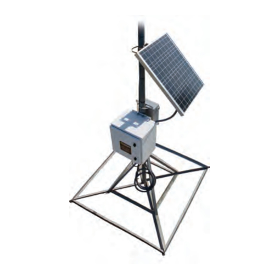
- Page 13 Figures Figure 1 – Solar Unit Figure 2 – AC-Powered Wall Unit Figure 3 – Gateway Wall Mount Installation Figure 4 – Gateway Stand Installation Figure 5 – Gateway Pole Installation Figure 6 – N_SIGHT Main Menu Figure 7 – Settings Menu Figure 8 –...
- Page 14 Figures Figure 31 – Attaching Coax Cable Figure 32 – Weatherizing RF Antenna Figure 33 – Using Mounting Brackets Figure 34 – Installing Pole Brackets Figure 35 – Battery Box Installed Figure 36 – Battery and Wiring Figure 37 – Gateway Solar Panel Figure 38 –...
- Page 15 Figures Figure 62 – Adjust Tilt Angle Figure 63 – Attach Ground Wire Figure 64 – RF Antenna Cable Figure 65 – Weatherized RF Port Figure 66 – Power Cable Figure 67 – UPS Attached to a Large Pole Figure 68 – UPS Attached with Clamps Figure 69 –...
- Page 16 Figures Figure 93 – System LEDs Figure 94 – Modem Front View Figure 95 – Modem Back View Figure 96 – Cellular Modem Power Plug Figure 97 – Report Now Button Figure 98 – Magnetic Declination U.S. Figure 99 – Solar Power Zones Figure 100 –...
- Page 17 Tables Table 1 – Types of Gateway Installations Table 2 – Cellular Modem Parts List Table 3 – Ethernet Parts List Table 4 – Recommended Tools and Materials Table 5 – Determining the Configuration Options Table 6 – Installing the Gateway Large Pole Mount System Table 7 –...
- Page 18 Tables Table 31 – Acceptable Coax Cables Table 32 – Coaxial Order Matrix Table 33 – Installation Materials Needed Table 34 – CDMA Bands & Speeds Supported by Vanguard 3000 Table 35 – GSM Bands and Speeds Supported by Vanguard 3000 Table 36 –...
-
Page 19: Chapter 1: Overview
The R900 Gateway v4 (Gateway) is a fixed network data collector that collects meter reading data from Neptune's R900 ® meter interface unit (MIU). Data from the MIU is stored in the Gateway until it synchronizes with the N_SIGHT™ PLUS host software by means of web services. -
Page 20: General Product Overview
Regardless of whether you are installing the Gateway in an indoor or outdoor environment, Neptune provides a kit for five types of setups as detailed in Table 1 on the facing page. A cellular modem or Ethernet connection is used for backhaul communications. -
Page 21: Site Considerations
Chapter 1: Overview Table 1 – Types of Gateway Installations Solar-Powered AC-Powdered Wall Stand Pole Ranging from 2 inch to 16 inch in diameter. Site Considerations One of the first installation considerations is where to locate the Gateway. The first priority in choosing a site is selecting a line- of-sight location not obstructed by trees, hills, mountains, or anything else that would block the RF communications from the MIUs in that area. -
Page 22: Mounting Configurations
Chapter 1: Overview Mounting Configurations Wall Mount A wall-mounted Gateway can be attached directly on a wall or mounted to a strut channel that is affixed to a wall. Figure 3 – Gateway Wall Mount Installation The Gateway allows for a cellular modem or Ethernet connection for backhaul communication. -
Page 23: Pole Installation
Chapter 1: Overview Pole Installation The pole installation is used with an outdoor free-standing pole ranging from 2 inches to 16 inches in diameter, such as a utility pole. Refer to Figure 5 for typical pole configuration. Figure 5 – Gateway Pole Installation The Gateway allows for a cellular modem or Ethernet connection for backhaul communication. -
Page 24: Ac Unit
Accessories are available. Contact your Neptune sales representative for details. Some installation sites have a weak cellular signal (-90 dBm or weaker). An optional external cellular antenna mounting kit (Neptune Part No. 13147-000) can increase the signal strength in these cases. Ethernet The following list includes the parts needed for the Ethernet connection. -
Page 25: Provisioning The Cellular Service To The Gateway
Chapter 1: Overview Provisioning the Cellular Service to the Gateway To activate the cellular service to the Gateway, complete the following steps. 1. Select your preferred wireless service provider. When selecting a carrier, choose a wireless service provider that provides service in the area of the installation site and is approved by your utility. - Page 26 Chapter 1: Overview This page intentionally left blank. R900 Gateway Installation and Maintenance Guide...
-
Page 27: Chapter 2: Activating Gateway In The Host Software
Chapter 2: Activating Gateway in the Host Software This chapter provides information on how to activate the Gateway. Step One Log on to the N_SIGHT PLUS server application through your web browser. Step Two Determine whether to use an existing Gateway server or add a new one to the N_SIGHT PLUS host software. -
Page 28: Figure 8 - Table Maintenance Window
Chapter 2: Activating Gateway in the Host Software 3. Select Gateway Servers from the Table Maintenance drop- down menu. See Figure 8. Figure 8 – Table Maintenance Window The Table Maintenance window appears. See Figure 9. Figure 9 – Gateway Detail Window 4. -
Page 29: Step Three
Chapter 2: Activating Gateway in the Host Software Although the server needed is already created, complete Step 5 which follows. 5. Complete the required fields of the Table Details tab. See Figure 10 – page 10. Field Enter Server Name Type the server name. -
Page 30: Figure 13 - New Collector/Gateway Dialog
Chapter 2: Activating Gateway in the Host Software The following dialog appears. Figure 13 – New Collector/Gateway Dialog 3. Click Gateway. See Figure 14. The following dialog appears. Figure 14 – Collector Type 4. Select V4 from the drop-down menu. See Figure 15. Figure 15 –... -
Page 31: Basic Information
Chapter 2: Activating Gateway in the Host Software 5. Select Yes or No to copy an existing Gateway. See Figure 16. Yes Allows you to select the Gateway to copy configuration settings. Allows you to build a new configuration. Figure 16 – Copy an Existing Gateway Basic Information 1. -
Page 32: Location
Chapter 2: Activating Gateway in the Host Software 2. Complete the required fields on the Basic Information dialog. See Figure 17 – page 13. Field Enter Serial Number Type the serial number from the Gateway (GPV4xxxxx). Site ID Completed by the N_SIGHT PLUS host software. Description Type reference name for location (5thStTank,WTP1). -
Page 33: Static Ip
Chapter 2: Activating Gateway in the Host Software Static IP 1. Click Next and the Static IP dialog appears. See Figure 19. Figure 19 – Static IP Window 2. Select Yes or No. If No is selected, go to "Web Service" on the next page. If Yes is selected, click Next and the following dialog appears. -
Page 34: Web Service
Select same Web server. Network Time Protocol (NTP) Provide NTP server Web address. It can be a public NTP (ex: time.nist.gov) or a Server Neptune NTP. Transfer Interval Set to minutes between uploads (default: 359) six hours. R900 Gateway Installation and Maintenance Guide... -
Page 35: Read Reporting
Chapter 2: Activating Gateway in the Host Software Read Reporting 1. Click Next and the following dialog appears. Figure 22 – Read Reporting 2. Leave all values set to zero. Command Polling 1. Click Next and the following dialog appears. Figure 23 – Command Polling 2. -
Page 36: Process Configuration
Chapter 2: Activating Gateway in the Host Software Process Configuration 1. Click Next and the following dialog appears. Figure 24 – Process Configuration 2. Verify that the fields have the following default values. Download Extension - .tar Rename Extension - .xxx Data Extension - .dat Advanced Options 1. -
Page 37: Figure 26 - Collectors Search Window
Chapter 2: Activating Gateway in the Host Software 2. Scroll through the dialog until you see the Advanced Options. 3. Select the meter type from a drop-down list next to the Meter Type field. 4. Select 1 for the value for the Keep Modem On field. 5. -
Page 38: Step Four
Chapter 2: Activating Gateway in the Host Software Step Four Transfer the configuration file to a USB drive. 1. Select the Gateway that was created. 2. Click Build USB and the following dialog appears. Figure 27 – Save USB Build 3. Click OK. The R900_Configcfg file is transferred to a USB flash drive.. -
Page 39: Chapter 3: General Installation Information
Chapter 3: General Installation Information Use the information in this chapter to ensure that you are properly prepared for installing Gateway units according to the guidelines provided in this guide. Preparation This section describes the necessary procedures to prepare for the installation of new Gateway units, and must be completed before hardware installation occurs. -
Page 40: Electrical Specifications
Chapter 3: General Installation Information Electrical Specifications DC Power (solar or UPS) 12 VDC 0.46 A nominal (1 A peak) Power Consumption 5.6 W nominal (12 W peak) Environmental Conditions Operating Temperature -22° to 140° (-30° to 60°C) Storage Temperature -40°... -
Page 41: Ups Specifications
Chapter 3: General Installation Information UPS Specifications Manufacturer TSI Power Part No. OUTDOOR-DC-UPS-8009 w/option BH-5 AC Input 120V 60Hz (100 - 140 VAC range) Output 12 VDC Dimensions 10.0 W x 12.0 H x 6.0 in. D (25.4 x 30.5 x 15.2 cm) Weight 30 lbs. -
Page 42: Battery Enclosure
Chapter 3: General Installation Information 220 W Option Rated Power 220 W Rated Voltage (Vmp) 17.4 V Rated Current (Impt) 12.6 A Open Circuit Voltage (Voc) 22.0 V Short Circuit Current (Isc) 13.2 A Dimensions 52.0 x 48.0 in. (132 x 121.9 cm) Weight 42.8 lbs. -
Page 43: Rf Antenna Specifications
.22 sq ft. Termination N Female Mounting Base Diameter 1.3125 (5/16) in. Mounting Method Mast or wall mounted Mounting Hardware MMK4 heavy duty mast mount (sold separately). Optional wall mounting kit (Neptune Part No. 13145-000) R900 Gateway Installation and Maintenance Guide... -
Page 44: Storage
After unpacking the Gateway, inspect it for damage. If any parts of the Gateway appear to be damaged or prove to be defective upon installation, notify your Neptune representative. If the unit or item needs to be returned, use the original cardboard box and packing material. - Page 45 Chapter 3: General Installation Information Table 4 – Recommended Tools and Materials - Continued Item Description/Recommendation Hammer Channel locks T27 Torx Pin-Head Tool (Wiha Part No. 36283) Ultraviolet (UV) - 8 in. and 12 in. (20 cm and 30 cm) Securing coax cable stable cable ties Coax ground...
-
Page 46: Safety And Preliminary Checks
Chapter 3: General Installation Information The following images are examples of the coax ground kit and coax hoisting grips. Figure 28 – Coax Ground Kit Figure 29 – Coax Hoisting Grips Safety and Preliminary Checks Always follow your company's safety practices and installation guidelines when installing your Gateway unit. -
Page 47: Chapter 4: Installation Of The Gateway
Chapter 4: Installation of the Gateway This chapter contains sections detailing the installation instructions for the Gateway installation options. "Mounting RF Antenna to a Pole or Stand" below "Mounting the Battery Box" on page 32 "Attaching the Solar Panel" on page 34 "Mounting the Gateway - Solar Configuration"... -
Page 48: Mounting The Rf Antenna
Chapter 4: Installation of the Gateway Mounting the RF Antenna To mount the RF antenna to a pole or a stand, complete the steps which follow. For more information go to "RF Antenna and Coax Installation" on page 101. 1. Assemble the stand in accordance with the manufacturer's instructions. -
Page 49: Figure 32 - Weatherizing Rf Antenna
Chapter 4: Installation of the Gateway 4. Weatherize the RF antenna connection using the weatherizing kit specified in Table 4 on page 26. See Figure 32. Figure 32 – Weatherizing RF Antenna 5. Mount the RF antenna pole using antenna mounting brackets. See Figure 33 6. -
Page 50: Mounting The Gateway - Solar Configuration
Chapter 4: Installation of the Gateway Mounting the Gateway - Solar Configuration This section provides instructions for mounting the Gateway with a solar configuration. Mounting the Battery Box Before installing a solar-powered unit, choose a non-shaded location that faces true south. Determine true south by using a magnetic compass corrected for magnetic declination. -
Page 51: Figure 35 - Battery Box Installed
Chapter 4: Installation of the Gateway 2. Hang the battery box without batteries on the upper mounting bracket. See Figure 35. 3. Attach the lower bracket to the battery box using the 5/16-inch carriage bolts. 4. Tighten bolts using a 1/2-inch wrench to 10-12 ft.lbs. -
Page 52: Attaching The Solar Panel
Chapter 4: Installation of the Gateway Attaching the Solar Panel The solar panel is mounted to the Gateway stand or to a pole. See Figure 37. This panel allows the Gateway to operate using energy generated by the sun. Figure 37 – Gateway Solar Panel The solar panel comes with mounting brackets already attached, and is pre-terminated with 15 feet (#10 AWG) wire in flexible non-metallic conduit. -
Page 53: Figure 39 - Solar Panel Tilt Angle
The pole/wall mounting bracket is included with the Gateway. Contact your Neptune sales representative to order the stainless steel clamps for mounting the Gateway to a pole. R900 Gateway Installation and Maintenance Guide... -
Page 54: Wiring The Solar Panel
Chapter 4: Installation of the Gateway To mount the Gateway to a pole or stand, complete the following steps. 1. Position the Gateway so that the top of the box is approximately level with the battery box. See Figure 40. Figure 40 –... -
Page 55: Wiring The Battery Box
Chapter 4: Installation of the Gateway 1. Feed the flexible conduit wiring from the solar panel to the back of the battery box. See Figure 42. 2. Connect the green ground (GND) solar panel to the green GND lead in the battery box. 3. -
Page 56: Wiring The Gateway
Chapter 4: Installation of the Gateway 2. Insert the DC power cable through the connector hub. 3. Tighten the connector hub using a crescent wrench to secure the cable. See Figure 44. Figure 44 – Connector Hub Insert enough cable so that it can be terminated to the load terminals inside the battery box. -
Page 57: Attaching The Rf Antenna Cable
Chapter 4: Installation of the Gateway 1. Locate the lightning protection system ground wire for the site. 2. Connect the external ground lug of the Gateway to the lightning protection system ground wire for that site. See Figure 46. Use #4 or #6 AWG copper wire with a minimum temperature rating of 74°C. -
Page 58: Attaching The Power Cable
Chapter 4: Installation of the Gateway Attaching the Power Cable Attach the power plug to the Gateway by pushing and rotating the circular power connector clockwise to engage it. Figure 48 – Power Cable Do not weatherize the power connection. The power connector is IP68-rated and does not require weatherization wrap. -
Page 59: Activating The Gateway System
Chapter 4: Installation of the Gateway After the Gateway is wired, the next stage is to apply the ballast material (for example, concrete blocks). To apply the ballast to the stand, complete the following steps. 1. Refer to "Ballast Requirements" on page 99 in Appendix B to determine the adequate amount of ballast for your installation. -
Page 60: Configuring The Cellular Modem
Chapter 4: Installation of the Gateway 5. Open the Gateway. 6. Watch for LED activity. See "Installation Troubleshooting" on page 70 for definitions and status indications of LED lights. There is approximately a three-minute delay before the Gateway becomes fully functional. Figure 51 –... -
Page 61: Configuring The Gateway
Chapter 4: Installation of the Gateway Configuring the Gateway The Gateway can be configured by either using a USB flash drive or the N_SIGHT PLUS host software, as delineated in Table 5. Table 5 – Determining the Configuration Options If you have ... Use this configuration option ... -
Page 62: Installing A Large Pole Mount System
Chapter 4: Installation of the Gateway Installing a Large Pole Mount System This section provides the steps (see Table 6) to mount the Gateway system to a large pole. The instructions to mount the Gateway system to a large pole are very similar to the instructions for installing a stand system. -
Page 63: Mounting The Rf Antenna To A Large Pole
Chapter 4: Installation of the Gateway Mounting the RF antenna to a Large Pole Mount the RF antenna to a 5-inch to 16-inch (12.7 to 40.65 cm) diameter pole by completing the following steps. 1. Mount the RF antenna bracket to the large pole using the two stainless steel Snaplock clamps. -
Page 64: Mounting The Gateway To A Large Pole
Chapter 4: Installation of the Gateway 3. Attach the coax cable to the base of the RF antenna. See Figure 54. Figure 54 – Coax Cable Attached Verify that the coax cable type is correct for the run length. See "Coaxial Cable Lengths for the Gateway" on page 103. 4. -
Page 65: Mounting The Battery Box To A Large Pole
Figure 56 – Gateway Pole Hardware The pole/wall mounting bracket is included with the Gateway. Contact your Neptune sales representative to order the stainless steel clamps for mounting the Gateway to a pole. 2. Insert the clamps through the slots on the mounting bracket. -
Page 66: Figure 59 - Pole Hardware
Chapter 4: Installation of the Gateway 3. Install the brackets onto the pole using stainless steel clamps. Be sure that the brackets are spaced 12.75 inches (32.39 cm) apart. See Figure 59. 4. Lift the battery box then lower it so that the flange on the top rear of the box slides over the flange of the top bracket and locks in place. -
Page 67: Mounting The Solar Panel To A Large Pole
Chapter 4: Installation of the Gateway Mounting the Solar Panel to a Large Pole Mount the solar panel to a 5-inch to 16-inch (12.7 cm to 40.64 cm) diameter pole by completing the following steps. See "Solar Power Information" on page 77. 1. -
Page 68: Attaching Ground Wire
Chapter 4: Installation of the Gateway Attaching Ground Wire Attach the ground wire by completing the following steps. 1. Locate the lightning protection system ground connection for the site. 2. Connect the external grounding lug of the Gateway to the lightning protection system for that site. See Figure 63. -
Page 69: Weatherizing The Rf Antenna Connection
Chapter 4: Installation of the Gateway Weatherizing the RF Antenna Connection Complete the following instructions to weatherproof the RF antenna. 1. Weatherize the RF antenna port connection using the weatherizing kit, as described in "Recommended Tools and Materials" on page 26. 2. -
Page 70: Configuring The Cellular Modem
Chapter 4: Installation of the Gateway Configuring the Cellular Modem See "Configuring the Cellular Modem" on page 108 of Appendix D. Configuring the Gateway The Gateway can be configured by either using a USB flash drive or the N_SIGHT PLUS host software, as delineated in Table 7. Table 7 –... -
Page 71: Installing The Ups To A Large Pole
Chapter 4: Installation of the Gateway 6. After removing the USB flash drive, the Gateway reboots. Allow the Gateway approximately three minutes to complete the boot sequence. 7. LED D501 (BF MIU Activity) begins flashing green to indicate that the Gateway has finished booting and is receiving MIU readings. -
Page 72: Connecting Power To The Ups
Chapter 4: Installation of the Gateway Connecting Power to the UPS This section contains the instructions for connecting the UPS to the Gateway. The UPS requires 120 VAC on the input and provides 12 VDC output to the Gateway. Connect the UPS according to the manufacturer's instructions. -
Page 73: Installing A Wall Mount System
Chapter 4: Installation of the Gateway Installing a Wall Mount System The following sections contain the instructions needed to install a wall-mounted system. Table 8 – Installing a Wall Mount System Complete Instructions Cellular Ethernet "Mounting the Gateway to a Wall" below "Mounting the RF Antenna and Antenna Mast"... -
Page 74: Installing The Ups
Chapter 4: Installation of the Gateway Installing the UPS To install the UPS, complete the following steps. 1. To mount the UPS to a wall near the Gateway, use corrosion-resistant hardware through the four holes provided in the mounting bracket. See Figure 71. Figure 71 –... -
Page 75: Connecting The Ground Wire
Chapter 4: Installation of the Gateway The AC input (to the UPS) must have a readily accessible disconnect device installed. 4. Wire the 12 VDC output through the upper knockout hole. 5. Install the cover on the UPS and secure with the two cover screws. -
Page 76: Connecting The Cables To The Gateway
Chapter 4: Installation of the Gateway Connecting the Cables to the Gateway The RF antenna is attached to an outside structure and is connected to the Gateway as follows. 1. Attach the RF antenna cable to the bottom of the unit. See Figure 75. -
Page 77: Mounting The Rf Antenna And Antenna Mast
Chapter 4: Installation of the Gateway When the Gateway's Ethernet port is not in use, cover with the included protective guard (CONEC P/N:17- 10002). 6. Illustrates the completed Gateway and UPS wall installation. Figure 78 – Wall Installation Mounting the RF Antenna and Antenna Mast The RF antenna mast and stand must be grounded to the same grounding electrode used for the building's electrical system to ensure that all exposed, non-current-... -
Page 78: Mounting The Antenna Mast To The Building
20 pounds loading. The model of pole bracket shown can be different than what Neptune supplies. Please contact Neptune Customer Support if you have any questions. 4. Place antenna mast pole within the bracket. -
Page 79: Mounting Rf Antenna To Antenna Mast
Chapter 4: Installation of the Gateway Mounting RF Antenna to Antenna Mast To mount the RF antenna to the antenna mast, complete the following steps. 1. Attach antenna mounting brackets to mast. See Figure 81. Figure 81 – Mounting Brackets 2. Attach coax cable to RF antenna. See Figure 82. Figure 82 –... -
Page 80: Figure 84 - Rf Antenna To Mast
Chapter 4: Installation of the Gateway 5. Mount the RF antenna to the antenna mast using antenna mounting brackets. See Figure 84. Figure 84 – RF Antenna to Mast 6. Secure the coaxial cable every 2 feet along the mast using UV-stable wire ties. See Figure 85. Figure 85 –... -
Page 81: Connecting The Ethernet Cable
Chapter 4: Installation of the Gateway Connecting the Ethernet Cable This step is only for kits using the Ethernet backhaul. If you are using a cellular modem, then skip this section. Prior to connecting the Ethernet port, you must run an Ethernet cable to the location of the Gateway. -
Page 82: Configuring The Gateway
Chapter 4: Installation of the Gateway 3. Assemble the Ethernet plug according to the instructions included. See Figure 88. Figure 88 – RJ45 Ethernet Plug 4. Terminate the Ethernet jack to the Ethernet cable. See Figure 89. Refer to "Ethernet Termination" on page 114 of Appendix D. -
Page 83: Chapter 5: Gateway Monitoring
Chapter 5: Gateway Monitoring This section contains basic techniques that allow you to diagnose and resolve unusual activity that you may notice when monitoring your Gateway system. Monitoring the Gateway N_SIGHT PLUS host software allows the user to monitor each Gateway. See Figure 91. -
Page 84: Files Missing For Days
If files are missing for a number of days, complete the following steps before calling Neptune Customer Support. 1. Try to reboot the Gateway that has missing files by disconnecting the black power connector from the bottom of the Gateway unit. -
Page 85: Processing Files
Chapter 5: Gateway Monitoring 4. Insert the USB flash drive in the Gateway USB port. The LED lights underneath the USB port begin to flash red alternately, in a railroad or wigwag pattern, indicating that the files are loading to the USB flash drive from the Gateway. The amount of data the Gateway has stored determines the amount of time it takes to load the files to the USB flash drive. -
Page 86: Up-To-Date Files
Chapter 5: Gateway Monitoring Up-to-Date Files If you see files that are up-to-date and have been processed but the file size is 0KB, this means that the Gateway is communicating well with the N_SIGHT PLUS host software but it is not receiving readings. This usually indicates there is a problem with the receiver. -
Page 87: Chapter 6: Troubleshooting
Chapter 6: Troubleshooting This section provides possible symptoms, areas of focus, and actions you can take to resolve problems that could arise with your Gateway unit. Performance Troubleshooting Refer to the following table to troubleshoot performance or failure issues. Table 9 – Performance Troubleshooting Problem/Failure Recommended Action N_SIGHT PLUS host... -
Page 88: Installation Troubleshooting
Chapter 6: Troubleshooting Installation Troubleshooting Checking UPS Status LEDs Complete the following steps to check the UPS status. 1. Remove the two screws that secure the UPS cover. 2. Remove the cover. 3. Verify that the internal power switch is on. 4. Verify the status LEDs inside the UPS. See Table 10. Table 10 –... -
Page 89: Checking Power And Receiver
Chapter 6: Troubleshooting Checking Power and Receiver It is a good practice to check the main power and make sure it is within specification. If there are no power indications on the Gateway, perform the following procedure. Verify Main Power The Gateway uses the same DC power cable (Part No. -
Page 90: Verifying The Digital Board
Chapter 6: Troubleshooting Figure 93 – System LEDs Verifying the Digital Board During initial startup, wait approximately three minutes for the Gateway to complete the booting. LED D514 displays green when power is applied. Under normal operation LED D514 blinks green in a repeating pattern of eight seconds steadily-lit green, then one-half second off, indicating normal operations. -
Page 91: Checking Cellular Modem Connectivity
Chapter 6: Troubleshooting Checking Cellular Modem Connectivity There are LED lights located on the digital and RF board that should be lit as the unit is powered on. See Figure 93 – page 72. LED lights on the Ethernet connector (EF Ethernet J1003) should be flashing or steadily lit indicating that the Ethernet connection is good. -
Page 92: Verifying Cellular Modem Power
5. After you have verified that all of the steps have been completed and you are still having issues with the unit operating properly, call Neptune Customer Support at (800) 647-4832 for assistance with further diagnosis. See "Contacting Customer Support" on the facing page. -
Page 93: Report Now Function
Within North America, Neptune Customer Support is available Monday through Friday, 7:00 AM to 5:00 PM Central Standard Time by telephone, email, or fax. By Phone To contact Neptune Customer Support by phone, complete the following steps. 1. Call (800) 647-4832. 2. Select one of the following options. -
Page 94: By Fax
A description of any actions taken to correct the issue. By Fax To contact Neptune Customer Support by fax, send a description of your problem to (334) 283-7497. Please include on the fax cover sheet the best time for a customer support specialist to contact you. -
Page 95: Appendix A Solar Power Information
Appendix A Solar Power Information Appendix A provides information on the installation of the solar panels. Installation Considerations for Solar Panels Solar panels should be installed in a location where they receive maximum sunlight throughout the year. When choosing a site, avoid trees, buildings, or obstructions which could cast shadows on solar panels especially during the winter season when the arc of the sun is lowest over the horizon. -
Page 96: Specific Tilt Angle
Appendix A Solar Power Information 5. Orient your solar panel in direction of true south (or north if applicable) as determined above. 6. A declination chart for North America is provided in Figure 98 – on the facing page for assistance in determining the appropriate correction for other sites. -
Page 97: Magnetic Declination For The United States
Appendix A Solar Power Information Magnetic Declination for the United States The map of the United States in Figure 98 illustrates the magnetic declination of the United States. Magnetic declination refers to the angle between the Magnetic North (MN, compass north) and True North (TN) at any given latitude/longitude. -
Page 98: Selecting The Correct Solar Power System
Table 13 – Solar Power System Selection Solar Power System Solar Panel Solar Power Zone Selection Wattage Dimensions Neptune Part No. A, B, C, and D 150 W 26 inch x 58 inch 13068-200 (small pole/stand) 13068-400 (large pole) E and Canada 220 W... -
Page 99: Solar Power System Operation Summary
For example, if the site location falls on transition line D and E, choose the zone E solar power system recommendation. 4. For accessories, contact your Neptune sales representative for the most current information. Solar Power System Operation Summary When the installation of the system is complete, you can expect the following typical performance. -
Page 100: Troubleshooting The Solar Power System
Appendix A Solar Power Information When the no-sun availability period exceeds five days, the system disconnects the Gateway unit from the battery to prevent the battery from being discharged to the extreme. This happens when the battery voltage drops to 11.5 V, which is approximately 85% depth of discharge (DOD). -
Page 101: Troubleshooting The Solar Controller
Appendix A Solar Power Information Table 14 – Solar Power System Troubleshooting (continued) Problem Probable Cause Recommended Action Load low voltage Confirm that the battery voltage is above the LVD cutoff disconnect (LVD) trip on voltage of 11.5 V. If not, allow the battery to fully charge. the load controller LVD reconnects at 12.6 V. -
Page 102: Sunsaver Gen 2
Appendix A Solar Power Information The SunSaver-10L charge controller has two topology generations: Gen 2 and Gen 3. Both the SunSaver Gen 2 and SunSaver Gen 3 solar controllers ship with a jumper installed. This sets the controller for charging: The sealed valve, a regulated lead acid (VRLA) The absorbent glass mat (AGM) batteries, used by the solar power system... -
Page 103: Red Led
Appendix A Solar Power Information Red LED The SunSaver Gen 2 includes an LVD feature indicated by a red LED. Whenever the battery charge state falls below the LVD set- point (11.5V), the load is disconnected, and the red LED illuminates. -
Page 104: Battery Status Leds
Appendix A Solar Power Information Table 15 – Charging Status LED Definitions Color Indication Operating State None Off (with heartbeat Night Green On solid (with heartbeat Charging Flashing Error On solid (with heartbeat Critical error Status LED heartbeat indication flickers ON briefly every 5 seconds. Status LED heartbeat indication flickers OFF briefly every 5 seconds. -
Page 105: Led Error Indications
Appendix A Solar Power Information LED Error Indications The following tables describe how to interpret the LED error indications. Table 17 – Charging Status LED Error Indications Error Condition LED Status Solar overload Flashing red High voltage disconnect Flashing red High temperature disconnect Flashing red Damaged local temperature sensor Solid red... -
Page 106: Prostar Controllers
Appendix A Solar Power Information ProStar Controllers There are four different ProStar controller models that may be installed in the solar power systems. PS-15 (15A rating) PS-15M (15A rating, with digital meter option included) PS-30 (30A rating) PS-30M (30A rating, with digital meter option included) Figure 102 –... -
Page 107: Battery Status
Appendix A Solar Power Information Battery Status For battery status indications, see Table 20. Table 20 – Battery Status LED Indicators LED Color Battery Status ON: indicates battery is near full charge. Green BLINKING : indicates PWM charging (regulation). Yellow ON: indicates battery at middle capacity. BLINKING: indicates a low charge state and a LVD warning. -
Page 108: Manual Disconnect
Appendix A Solar Power Information The digital meter operates from -30°C to +85°C. The values displayed are calibrated electronically in production and are accurate to within a few percent. If the Battery Sense is not connected, the voltage displayed is in error by the voltage drops in the battery wires. -
Page 109: Self-Diagnostics (Self-Test)
Appendix A Solar Power Information Self-Diagnostics (Self-Test) If the push button is held for four seconds, the ProStar goes into automatic self-diagnostics. The button must be released to start the self-test. See Table 22 The push button can be used to toggle through the displays faster. -
Page 110: Terminate The Self Test
Appendix A Solar Power Information Table 23 – Fault Error List Display Error Condition Rotary switch battery selection failure Voltage reference test failed (circuit, malfunctions) Solar array current fault (circuit, (FET Load FETs off test (load connection, FETs shorted) Load current fault (circuit, FETs) Load FETs on test (load circuit, FETs open) Internal temp sensor out of range high Internal temp sensor out of range low... -
Page 111: Additional Troubleshooting Information
Appendix A Solar Power Information Additional Troubleshooting Information For additional troubleshooting information, refer to the ProStar Solar Controller Operations Manual. This should be included with the solar power system. The manual is also available online from Morningstar. Troubleshooting the Solar Panel's Battery You can measure both the batteries voltage open circuit (Voc) and voltage under charge (Vuc). -
Page 112: Table 26 - Battery Load Voltage By Dod
Appendix A Solar Power Information If an individual battery does not hold a voltage of a least 12.6 VDC open circuit after a full charge and a three-hour wait period under no load, you could have a damaged cell and require a battery replacement. -
Page 113: Solar Panel Troubleshooting
Appendix A Solar Power Information Solar Panel Troubleshooting This section provides information that can assist with troubleshooting problems with a solar panel. Decreased Solar Panel Output The solar panel is designed for long life and requires very little maintenance. Under most weather conditions, normal rainfall is sufficient to keep its glass surface clean and free of debris. -
Page 114: Verifying Solar Panel Output
Appendix A Solar Power Information Verifying Solar Panel Output If the solar panel is unobstructed, unshaded, at the correct tilt angle, and in full light between 10 a.m. and 3 p.m., you can verify the solar panel's performance per the nameplate ratings for Voc and short circuit current (ISC) as follows. -
Page 115: Table 28 - Sunlight By Time Of Day In Summer
Appendix A Solar Power Information Table 28 provides the degrees of sunlight at various times on a clear, sunny day in the summer. Table 28 – Sunlight by Time of Day in Summer Degree of Sunlight Time Sun Capacity 7:00 a.m. - 9:00 a.m. 10 - 30% 9:00 a.m. - Page 116 Appendix A Solar Power Information This page intentionally left blank. R900 Gateway Installation and Maintenance Guide...
-
Page 117: Appendix B Ballast
Appendix B Ballast This appendix discusses the requirements for a proper ballast for the Gateway stand (a non-penetrating roof mount). Ballast Requirements Prior to installation, verify that the supporting structure (for example, rooftop) has been investigated and found capable of withstanding all loads imposed by the proposed Gateway system installation. -
Page 118: Rohn Industries Stand
Appendix B Ballast Install a roof pad beneath the stand to protect the roof surface. For a 5 ft. x 5 ft. (1.5 m x 1.5 m) ROHN stand, use ROHN Part No. R-JRMPAD or JRMPAD. ROHN Industries Stand The ROHN-JRM stand ships disassembled on one skid and weighs approximately 50 lbs when assembled. -
Page 119: Appendix C Rf Antenna And Coax Installation
This appendix provides information about how to install the RF antenna and coax cable. Neptune recommends that you consult with a qualified installer on the design and installation of the antenna system. If the installer is already familiar with the site and the existing equipment, this can make the installation go more smoothly. -
Page 120: Site Recommendations
Managed antenna sites can require additional equipment, and might dictate how an installation is to be performed. Follow the site's requirements as long as the installation meets Neptune's minimum requirements. Antenna Requirements Consider the following. The antenna, if mounted on the side of a tower or other supporting structure, must be mounted so that it is at least 5 feet away from the structure. -
Page 121: Feed Line Overview
> 100 ft. Andrew Part Number: AVA5-50 or AVA5-50FX You can order coax cable assemblies already terminated as accessories from Neptune or purchased from companies such as Tessco Technologies, Talley Communications, and Hutton Communications. Each end must be terminated with an N-male type connector. -
Page 122: Table 32 - Coaxial Order Matrix
Appendix C RF Antenna and Coax Installation Table 32 – Coaxial Order Matrix Loss/100 ft. Coax Neptune Manufacturer Description Bend @ 900 Length Lengths Part No. Part No. Radius ≤ 60 ft. - LMR-400-UF 4.7 dB 40 ft. 1 in. -
Page 123: Feed Line Requirements
See "Coaxial Cable Lengths for the Gateway" on page 103. The installation instructions for the Heliax Coaxial Cable are provided by Andrew. See Bulletin 17800B Revision C. Neptune can supply a PDF copy by request through Customer Support. R900 Gateway Installation and Maintenance Guide... -
Page 124: System Certification
Appendix C RF Antenna and Coax Installation Table 33 – Installation Materials Needed Items Description/Recommendation Securing Coax Cable Cable clips/coax hangers - for 1/2 inch or 7/8 inch UV-Stable cable ties 8 inch - 12 inch (20.32 cm- 30.48 cm) Weatherzing Kit Pick one of the following: PolyPhasor P/N: WK-1... -
Page 125: Appendix D Cellular And Ethernet Considerations
Appendix D Cellular and Ethernet Considerations This appendix provides information on the cellular modem used with the Gateway and the Ethernet. Cellular Modem Overview CalAmp's Vanguard 3000™ modem is designed for operation on both GSM and CDMA networks. It offers more choices and redundancy in carrier networks. Table 34 –... -
Page 126: Configuring The Cellular Modem
Appendix D Cellular and Ethernet Considerations Table 36 – Certifying Carriers by Nation United States Canada Mexico AT&T Rogers Verizon Bell Telus Configuring the Cellular Modem You can configure CalAmp's Vanguard 3000 modem to operate in either a GSM or CDMA network. To manually configure the cellular modem for the Gateway, you need a Vanguard 3000 modem from CalAmp, and then complete the steps to configure it. -
Page 127: Figure 104 - Cellular Modem Front - Status Leds
Appendix D Cellular and Ethernet Considerations To configure the cellular modem, complete the following steps. 1. Insert the SIM card, if applicable in the cellular modem's SIM card slot. For CalAmp Vanguard 3000, be sure to insert the SIM card gold side facing upward. 2. -
Page 128: Figure 106 - Unit Status Window
Appendix D Cellular and Ethernet Considerations Figure 106 – Unit Status Window 5. Verify the service is operational by opening an Internet browser page on the laptop. If you are able to successfully connect to a Web page, then the service is operational. If the service is not operational, contact the service provider. -
Page 129: Provisioning The Vanguard 3000 For Gsm
Carrier APN must be populated with a number that you obtain from the carrier. Cellular Modem Conversion Kit The cellular modem conversion kit (Neptune Part No. 13247-000) is an optional kit that's required to convert an Ethernet version Gateway to a cellular version Gateway in the field. -
Page 130: External Cellular Antenna Option
7. Connect the Ethernet cable from the J1003 BF Ethernet port on the Gateway to the LAN 1 Ethernet port on the cellular modem. 8. Connect the power cable (Neptune Part No. 13220-000) from the J5 port on the Gateway to the PWR port on the cellular modem. - Page 131 7. Install the external cellular antenna, mounting the antenna higher than the Gateway to obtain better service reception. An optional wall mounting kit (Neptune Part No. 13145-000) is available for the external cellular antenna. The kit includes a 5-foot mast and wall mount brackets.
-
Page 132: Ethernet Termination
Appendix D Cellular and Ethernet Considerations Ethernet Termination This section provides information on the termination of the Ethernet cable. Straight-Through Ethernet Cable For most installations of the Gateway, the straight-through Ethernet cable is used. Use a shielded category 5e or better Ethernet cable that is rated for outdoor use and is sunlight resistant, for example, Belden cable Part No. -
Page 133: Determining If You Need A Crossover Cable
Appendix D Cellular and Ethernet Considerations Figure 108 – Crossover Ethernet Cable Determining if You Need a Crossover Cable One method of determining if you need a crossover cable is to plug the Ethernet cable from the hub or modem into your laptop computer's Ethernet port. - Page 134 Appendix D Cellular and Ethernet Considerations This page intentionally left blank. R900 Gateway Installation and Maintenance Guide...
-
Page 135: Glossary
Glossary Abbreviation for alternating current, typically used in grid applications. Agonic lines Imaginary line on the surface of the earth connecting all points at which the declination of magnetic field of the earth is zero. Abbreviation for Amp-hour. Refers to battery capacity. Ammeter Instrument used to measure current. - Page 136 Glossary CDMA Code Division Multiple Access. A channel-access method used by various radio communication technologies that allow mutiple users to be connected over the same channel. Customer Information System. Converter Instrument used to convert power from AC:DC or DC:DC in a regulated manner. Abbreviation for direct current, typically used in battery applications.
- Page 137 Gateway Device that collects meter reading data from Neptune's absolute encoder register interfacing with Neptune's R900 MIU and transmits the data for collection. This unit receives the data and stores data to be downloaded through the N_SIGHT PLUS host software.
- Page 138 Glossary Joule Common unit of measurment for electrical energy. Joules equals watts per second. Light-Emitting Diode. Low voltage disconnect (load only). Abbreviation for Low Voltage Disconnect. A device in charge controllers that disconnects the load from the battery to protect from over discharge. Magnetic Declination The angle between the Magnetic North (MN, compass north) and True North (TN) at any given latitude/longitude.
- Page 139 Glossary MOSFET Metal-oxide semiconductor field-effect transistor is a specialized FET (field-effect transistor), and like all transistors, is used for switching or amplifying signals. N_SIGHT PLUS Host Software N_SIGHT PLUS is a software tool for gathering data packets containing information on remote MIU readings.
- Page 140 Glossary Common unit of measurement for electrical resistance. Abbreviation for Power Factor. Used to describe the quality of AC current in percentage. Abbreviation for Photovoltaic. Refers to the solar module that generates power from sunlight. Pulse Width Modulation. Is the most effective means to achieve constant voltage battery charging by switching the solar system controller's power devices.
- Page 141 Glossary Service. Time Domain Reflectometry. Ultraviolet light. Common unit of measurement for AC power. VA equals Volts x Amps x Power Factor. Voltage open circuit. Voltmeter Instrument used to measure voltage. Volts Common unit of measurement for electrical potential. Abbreviation for Volts Per Cell, used to describe the individual battery cell voltage. A 12V battery has 6, 2V cells.
- Page 142 Glossary Watt Common unit of measurement for DC power. Watts equals Volts x Amps. Wattmeter Instrument used to measure power. R900 Gateway Installation and Maintenance Guide...
-
Page 143: Index
Index carriage bolts 48 cellular considerations 107 modem 2, 5-6 power 2 configure 42, 52, 108 unit 6 connectivity 73 AC-powered system 32 conversion kit 111 accessories 1 power 74 activate 7, 9 service 7 analysis 1 charge controller 41 angle locator 35 CIS 1 antenna... - Page 144 Index electrical specifications 22 power 51 environment 2 installation 29 environmental conditions 22 kits 5 Ethernet 2, 4-6, 114 monitoring 65 considerations 107 mounting crossover, cable 114 large pole 46 plug 63 wall 55 port 59, 63 securing 40, 43 termination 114 servers 10 extension...
- Page 145 Index RF antenna and coax 101 materials 26 UPS 53, 56 mechanical specifications 22 wall mount 55 MEID 7 interference 3 missing files 66 isogonic lines 77 MIU 1 monitoring 65 mounting kit 5 antenna mast, to building 55 knockouts 33 brackets 56 latitude 14 negative declination 79...
- Page 146 Index positive declination 79 power cable, attaching 38 screwdriver 33 preparation 21 self-diagnostics 91 process configuration 18 serial number 14 propagation 3 settings 9 ProStar Controllers 88 sheet metal 55 battery status 89 SIM 6-7, 21, 109, 112 charging status 88 site 3, 102 digital meter 89 site id 14...
- Page 147 Index stand 99 troubleshoot 1, 69 configuration 4 installation 70 ROHN industries 100 modem 111 static IP 15-16 performance 69 default route 16 solar controller 83 name server 16 solar panel 93 nework 16 solar power 82 storage 26 true north 77 strut 4 true south 32, 48, 77 sunlight...
- Page 148 Index WAC 78 wall mount 4 weatherize 31, 39, 51, 61, 113 Web Host 16 web services 1 wind velocity 99 wireless service provider 7 Zones 5 R900 Gateway Installation and Maintenance Guide...
- Page 150 11570 Mèxico, Distrito Federal Fax: (905) 858-0428 T: (525) 55203 5294 / (525) 55203 5708 IM R900 Gateway v4 06.17 Part No. 13194-001 © Copyright 2006 - 2017, Neptune Technology Group Inc. Neptune is a registered trademark of Neptune Technology Group Inc.
Need help?
Do you have a question about the R900 v4 and is the answer not in the manual?
Questions and answers