Sign In
Upload
Manuals
Brands
Neptune Manuals
Gateway
13458-000
Neptune 13458-000 Manuals
Manuals and User Guides for Neptune 13458-000. We have
2
Neptune 13458-000 manuals available for free PDF download: Installation And Maintenance Manual
Neptune 13458-000 Installation And Maintenance Manual (150 pages)
Brand:
Neptune
| Category:
Gateway
| Size: 3 MB
Table of Contents
Table of Contents
7
Chapter 1: Overview
19
About this Guide
19
Conventions Used in this Manual
19
General Product Overview
20
Determining How to Install the Gateway
20
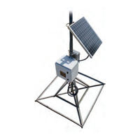
Figure 1 - Solar Unit
20
Figure 2 - AC-Powered Wall Unit
20
Site Considerations
21
Table 1 - Types of Gateway Installations
21
Mounting Configurations
22
Figure 3 - Gateway Wall Mount Installation
22
Figure 4 - Gateway Stand Installation
22
Gateway Stand
22
Wall Mount
22
Pole Installation
23
Gateway Kits
23
Solar Unit
23
Figure 5 - Gateway Pole Installation
23
AC Unit
24
Cellular Modem
24
Ethernet
24
Table 2 - Cellular Modem Parts List
24
Table 3 - Ethernet Parts List
24
Provisioning the Cellular Service to the Gateway
25
Chapter 2: Activating Gateway in the Host Software
27
Step One
27
Step Two
27
Figure 6 - N_SIGHT Main Menu
27
Figure 7 - Settings Menu
27
Figure 8 - Table Maintenance Window
28
Figure 9 - Gateway Detail Window
28
Figure 10 - Table Details
28
Step Three
29
Figure 11 - Collectors Tab
29
Figure 12 - Create Collector
29
Figure 13 - New Collector/Gateway Dialog
30
Figure 14 - Collector Type
30
Figure 15 - Select Type
30
Basic Information
31
Figure 16 - Copy an Existing Gateway
31
Figure 17 - Basic Information
31
Figure 18 - Gateway Location
32
Location
32
Figure 19 - Static IP Window
33
Figure 20 - Static IP Details
33
Static IP
33
Figure 21 - Web Service
34
Web Service
34
Command Polling
35
Figure 22 - Read Reporting
35
Figure 23 - Command Polling
35
Read Reporting
35
Advanced Options
36
Figure 24 - Process Configuration
36
Figure 25 - Advanced Options
36
Process Configuration
36
Figure 26 - Collectors Search Window
37
Step Four
38
Step Five
38
Figure 27 - Save USB Build
38
Chapter 3: General Installation Information
39
Preparation
39
Gateway Specifications
39
Electrical Specifications
40
Environmental Conditions
40
Mechanical Specifications
40
Gateway Stands
40
UPS Specifications
41
Solar Power System Specifications
41
Solar Panel
41
Battery
42
Battery Enclosure
42
RF Antenna Specifications
43
Storage
44
Unpacking
44
Tools and Materials
44
Table 4 - Recommended Tools and Materials
44
Safety and Preliminary Checks
46
Figure 28 - Coax Ground Kit
46
Figure 29 - Coax Hoisting Grips
46
Chapter 4: Installation of the Gateway
47
Mounting RF Antenna to a Pole or Stand
47
Mounting the RF Antenna
48
Figure 30 - Mounting Brackets
48
Figure 31 - Attaching Coax Cable
48
Figure 32 - Weatherizing RF Antenna
49
Figure 33 - Using Mounting Brackets
49
Mounting the Gateway - Solar Configuration
50
Mounting the Battery Box
50
Figure 34 - Installing Pole Brackets
50
Figure 35 - Battery Box Installed
51
Figure 36 - Battery and Wiring
51
Attaching the Solar Panel
52
Figure 37 - Gateway Solar Panel
52
Figure 38 - Solar Panel Attached
52
Figure 39 - Solar Panel Tilt Angle
53
Wiring the Solar Panel
54
Figure 40 - Mounting Bracket
54
Figure 41 - Positioning the Gateway
54
Wiring the Battery Box
55
Figure 42 - Back of Battery Box
55
Figure 43 - Feeding Conductor Wire
55
Wiring the Gateway
56
Connecting the Ground Wire
56
Figure 44 - Connector Hub
56
Figure 45 - Battery Box Wires
56
Attaching the RF Antenna Cable
57
Figure 46 - Ground Wire
57
Figure 47 - RF Antenna Cable
57
Attaching the Power Cable
58
Securing the Gateway
58
Applying the Ballast to the Stand
58
Figure 48 - Power Cable
58
Activating the Gateway System
59
Figure 49 - Concrete Block Ballast
59
Figure 50 - Activating the Battery
59
Configuring the Cellular Modem
60
Figure 51 - Gateway Cover Screws
60
Configuring the Gateway
61
Configuring the Gateway with the USB Flash Drive
61
Securing the Gateway
61
Table 5 - Determining the Configuration Options
61
Installing a Large Pole Mount System
62
Table 6 - Installing the Gateway Large Pole Mount System
62
Figure 52 - Large Pole Bracket
63
Figure 53 - RF Antenna Bracket
63
Mounting the RF Antenna to a Large Pole
63
Figure 54 - Coax Cable Attached
64
Figure 55 - Weatherized Connection
64
Figure 56 - Gateway Pole Hardware
65
Figure 57 - Slot on Mounting Bracket
65
Figure 58 - Battery Box Clamps
65
Mounting the Battery Box to a Large Pole
65
Figure 59 - Pole Hardware
66
Figure 60 - Mounted Battery Box
66
Mounting the Solar Panel to a Large Pole
67
Mounting the Gateway to a Large Pole
64
Attaching Cables for the Gateway
67
Figure 61 - Mounted Solar Panel
67
Figure 62 - Adjust Tilt Angle
67
Attaching Ground Wire
68
Attaching the RF Antenna Cable
68
Figure 63 - Attach Ground Wire
68
Figure 64 - RF Antenna Cable
68
Weatherizing the RF Antenna Connection
69
Connecting Power to the Gateway
69
Attaching the Power Cable
69
Figure 65 - Weatherized RF Port
69
Figure 66 - Power Cable
69
Configuring the Cellular Modem
70
Configuring the Gateway
70
Configuring the Gateway with the USB Flash Drive
70
Table 7 - Determining the Configuration Options
70
Figure 67 - UPS Attached to a Large Pole
71
Figure 68 - UPS Attached with Clamps
71
Connecting Power to the UPS
72
Figure 69 - Inside of the UPS
72
Installing the UPS to a Large Pole
71
Installing a Wall Mount System
73
Mounting the Gateway to a Wall
73
Figure 70 - Wall-Mounted Gateway
73
Table 8 - Installing a Wall Mount System
73
Figure 71 - UPS Mounted on a Wall
74
Figure 72 - UPS with VAC Input Wired
74
Installing the UPS
74
Connecting the Ground Wire
75
Figure 73 - 12 VDC Output Wired
75
Figure 74 - Ground Wire
75
Connecting the Cables to the Gateway
76
Figure 75 - Adding Gateway Cables
76
Figure 76 - Power Connector
76
Figure 77 - UPS Power Switch
76
Mounting the RF Antenna and Antenna Mast
77
Figure 78 - Wall Installation
77
Figure 79 - Securing Pole Bracket
78
Figure 80 - Lining up Second Pole Bracket
78
Mounting the Antenna Mast to the Building
78
Figure 81 - Mounting Brackets
79
Figure 82 - Coax Cable
79
Figure 83 - Weatherizing RF Antenna
79
Mounting RF Antenna to Antenna Mast
79
Figure 84 - RF Antenna to Mast
80
Figure 85 - Securing the Coax Cable
80
Connecting the Ethernet Cable
81
Figure 86 - Port Connection
81
Figure 87 - Feed-Through Assembly
81
Configuring the Gateway
82
Figure 88 - RJ45 Ethernet Plug
82
Figure 89 - Ethernet Plug Terminated
82
Figure 90 - Ethernet Plug Inserted
82
Chapter 5: Gateway Monitoring
83
Monitoring the Gateway
83
Figure 91 - Examples of N_SIGHT PLUS Gateway Monitoring
83
Files Missing for Days
84
Using a USB Drive to Retrieve Gateway .TAR Files
84
Processing Files
85
Up-To-Date Files
86
Chapter 6: Troubleshooting
87
Performance Troubleshooting
87
Table 9 - Performance Troubleshooting
87
Installation Troubleshooting
88
Checking UPS Status Leds
88
Table 10 - UPS Status Leds
88
Checking Power and Receiver
89
Figure 92 - Gateway Power Plug
89
Verify Main Power
89
Verify the RF Receiver
89
Verifying the Digital Board
90
Figure 93 - System Leds
90
Checking Cellular Modem Connectivity
91
Figure 94 - Modem Front View
91
Figure 95 - Modem Back View
91
Verifying Cellular Modem Power
92
Figure 96 - Cellular Modem Power Plug
92
Table 11 - Vanguard 3000 LED Functions
92
Report Now Function
93
Still Not Operating Properly
93
Contacting Customer Support
93
By Phone
93
Figure 97 - Report Now Button
93
By Fax
94
By Email
94
Appendix A Solar Power Information
95
Installation Considerations for Solar Panels
95
Magnetic Declination
95
Correction for Magnetic Declination and Solar Panel Tilt
95
Facing True South
95
Specific Tilt Angle
96
Figure 98 - Magnetic Declination U.S
97
Magnetic Declination for the United States
97
Selecting the Correct Solar Power System
98
Figure 99 - Solar Power Zones
98
Table 13 - Solar Power System Selection
98
Solar Power System Operation Summary
99
Troubleshooting the Solar Power System
100
Table 14 - Solar Power System Troubleshooting
100
Solar Charge Controller
101
Figure 100 - Gen 2 Solar Controller
102
Green LED
102
Sunsaver Gen 2
102
Charging Status LED
103
Figure 101 - Gen 3 Solar Controller
103
Red LED
103
Sunsaver Gen 3
103
Battery Status Leds
104
Table 15 - Charging Status LED Definitions
104
Table 16 - Battery Status LED Definitions
104
LED Error Indications
105
Table 17 - Charging Status LED Error Indications
105
Table 18 - Battery Status LED Error Indications
105
Troubleshooting the Solar Controller
101
Prostar Controllers
106
Charging Status
106
Figure 102 - Prostar Controllers
106
Table 19 - Charging Status LED Indicator
106
Battery Status
107
Digital Meter
107
Fault Indications
107
Table 20 - Battery Status LED Indicators
107
Table 21 - Fault Indications
107
Display Disconnects and Protections
108
Manual Disconnect
108
Self-Diagnostics (Self-Test)
109
Table 22 - Self-Test Display Examples
109
Select Battery Type
110
Table 23 - Fault Error List
110
Table 24 - Battery Type Switch Positions
110
Terminate the Self Test
110
Additional Troubleshooting Information
111
Table 25 - Voltages for SOC at 25°C
111
Troubleshooting the Solar Panel's Battery
111
Table 26 - Battery Load Voltage by DOD
112
Solar Panel Troubleshooting
113
Decreased Solar Panel Output
113
Table 27 - Sunlight by Time of Day in Winter
114
Verifying Solar Panel Output
114
Table 28 - Sunlight by Time of Day in Summer
115
Appendix B Ballast
117
Ballast Requirements
117
Table 29 - ROHN Stand Footprint Dimensions
117
Figure 103 - ROHN JRM23855 Stand
118
ROHN Industries Stand
118
Appendix C RF Antenna and Coax Installation
119
RF Antenna Overview
119
Mounting the Antennas
119
Table 30 - Mounting Antenna Considerations
119
Site Recommendations
120
Antenna Requirements
120
Feed Line Overview
121
Coaxial Cable Lengths for the Gateway
121
Table 31 - Acceptable Coax Cables
121
Table 32 - Coaxial Order Matrix
122
Feed Line Requirements
123
System Certification
124
Table 33 - Installation Materials Needed
124
Appendix D Cellular and Ethernet Considerations
125
Cellular Modem Overview
125
Table 34 - CDMA Bands & Speeds Supported by Vanguard 3000
125
Table 35 - GSM Bands and Speeds Supported by Vanguard 3000
125
Configuring the Cellular Modem
126
Equipment Required
126
Configuring the Modem
126
Table 36 - Certifying Carriers by Nation
126
Figure 104 - Cellular Modem Front - Status Leds
127
Figure 105 - Cellular Modem Back - Status Leds
127
Figure 106 - Unit Status Window
128
Modem Setup Troubleshooting
129
Provisioning the Vanguard 3000 for GSM
129
Cellular Modem Conversion Kit
129
Installing the Cellular Modem Conversion Kit
129
External Cellular Antenna Option
130
Installing the External Cellular Antenna
130
Ethernet Termination
132
Straight-Through Ethernet Cable
132
Crossover Ethernet Cable
132
Figure 107 - Straight-Through Ethernet Cable
132
Determining if You Need a Crossover Cable
133
Figure 108 - Crossover Ethernet Cable
133
Table 37 - Cable Color Code
133
Glossary
135
Index
143
Advertisement
Neptune 13458-000 Installation And Maintenance Manual (164 pages)
Brand:
Neptune
| Category:
Gateway
| Size: 3 MB
Table of Contents
This Page Intentionally Left Blank.
7
Table of Contents
7
Figures
15
Chapter 1: Overview
21
About this Guide
21
General Product Overview
21
Figure 1 - Solar Unit
21
Determininghow to Install the Gateway
22
Choosing the Installation Site of the Gateway
22
Table 1 - Types of Gateway Installations
22
Mounting Configurations
23
Wall Mount
23
Figure 3 - Gateway Wall Mount Installation
23
Gateway Stand
24
Pole Installation
24
Figure 4 - Gateway Stand Installation
24
Figure 5 - Gateway Pole Installation
24
Gateway Kits
25
Power Source
25
Solar Unit
25
AC Unit
25
Cellular Modem
25
Table 2 - Cellular Modem Parts List
25
Ethernet
26
Provisioning the Cellular Service to the Gateway
26
Table 3 - Ethernet Parts List
26
Chapter 2: Activating the Gateway in the Host Software
27
Step One
27
Step Two
27
Figure 6 - N_SIGHT ® Main Menu
27
Figure 7 - Settings Menu
27
Figure 8 - Table Maintenance Window
28
Figure 9 - Gateway Detail Window
28
Figure 10 - Table Details
28
Step Three
29
Figure 11 - Collectors Tab
29
Figure 12 - Create Collector
29
Figure 13 - New Collector / Gateway Dialog
30
Figure 14 - Collector Type
30
Figure 15 - Select Type
30
Basic Information
31
Figure 16 - Copy an Existing Gateway
31
Figure 17 - Basic Information
31
Location
32
Figure 18 - Gateway Location
32
Static IP
33
Figure 19 - Static IP Window
33
Figure 20 - Static IP Details
33
Web Service
34
Figure 21 - Web Service
34
Read Reporting
35
Command Polling
35
Figure 22 - Read Reporting
35
Figure 23 - Command Polling
35
Process Configuration
36
Advanced Options
36
Figure 24 - Process Configuration
36
Figure 25 - Advanced Options
36
Figure 26 - Collectors Search Window
37
Step Four
38
Step Five
38
Figure 27 - Save USB Build
38
Chapter 3: General Installation Information
39
Preparation
39
Gateway Specifications
39
Electrical Specifications
40
Environmental Conditions
40
Mechanical Specifications
40
Gateway Stand Specification
40
Table 4 - Electrical Specifications
40
Table 5 - Environmental Conditions
40
Table 6 - Mechanical Specifications
40
Table 7 - Gateway Stand Specification
40
UPS Specifications
41
Solar Power System Specifications
41
Solar Panel
41
160 W Option Specifications
41
Table 8 - UPS Specification
41
Table 9 - Solar Power System Specification - 160 W Option
41
220 W Option Specifications
42
Table 10 - Solar Power System Specification - 220 W Option
42
Battery Specifications
43
Battery Enclosure
43
Battery
43
RF Antenna Specifications
43
Table 11 - Solar Power System Specifications - Battery Enclosure
43
Table 12 - Solar Power System - Battery
43
Table 13 - RF Antenna Specifications
43
Storage
44
Unpacking
45
Tools and Materials
45
Table 14 - Recommended Tools and Materials
45
Safety and Preliminary Checks
47
Figure 28 - Coaxial Ground Kit
47
Chapter 4: Install the Gateway
49
Mounting RF Antenna to a Pole or Stand
49
Mounting the RF Antenna
49
Figure 30 - Mounting Brackets
49
Figure 31 - Attaching the Coaxial Cable
50
Figure 32 - Weatherizing the RF Antenna
50
Figure 33 - Mounting Brackets
51
Mounting the Gateway - Solar Configuration
52
Mounting the Battery Box
52
Figure 34 - Installing Pole Brackets
52
Figure 35 - Battery Box Installed
53
Figure 36 - Battery and Wiring
53
Attaching the Solar Panel
54
Figure 37 - Gateway Solar Panel
54
Figure 38 - Solar Panel Attached
54
Figure 39 - Solar Panel Tilt Angle
55
Mounting the Gateway
56
Figure 40 - Mounting Bracket
56
Figure 41 - Positioning the Gateway
56
Wiring the Solar Panel
57
Wiring the Battery Box
57
Figure 42 - Back of Battery Box
57
Figure 43 - Feeding Conductor Wire
58
Figure 44 - Connector Hub
58
Wiring the Gateway
59
Connecting the Ground Wire
59
Figure 45 - Battery Box Wires
59
Figure 46 - Ground Wire
59
Attaching the RF Antenna Cable
60
Attaching the Power Cable
60
Figure 47 - RF Antenna Cable
60
Figure 48 - Power Cable
60
Securing the Gateway
61
Applying the Ballast to the Stand
61
Activating the Gateway System
62
Figure 49 - Concrete Block Ballast
62
Figure 50 - Activating the Battery
62
Configuring the Cellular Modem
63
Figure 51 - Gateway Cover Screws
63
Configuring the Gateway
64
Configuring the Gateway with the USB Flash Drive
64
Securing the Gateway
64
Table 15 - Determining the Configuration Options
64
Installing a Large Pole Mount System
65
Mounting the RF Antenna to a Large Pole
65
Figure 52 - Large Pole Bracket
65
Figure 53 - RF Antenna Bracket
65
Figure 54 - Coaxial Cable Attached
66
Figure 55 - Weatherized Connection
66
Mounting the Gateway to a Large Pole
67
Mounting the Battery Box to a Large Pole
67
Figure 56 - Gateway Pole Hardware
67
Figure 57 - Slot on Mounting Bracket
67
Figure 58 - Battery Box Clamps
68
Figure 59 - Pole Hardware
68
Figure 60 - Mounted Battery Box
68
Mounting the Solar Panel to a Large Pole
69
Figure 61 - Mounted Solar Panel
69
Figure 62 - Adjust Tilt Angle
69
Attaching Cables for the Gateway
70
Attaching Ground Wire
70
Attaching the RF Antenna Cable
70
Figure 63 - Attach Ground Wire
70
Weatherizing the RF Antenna Connection
71
Connecting Power to the Gateway
71
Figure 64 - RF Antenna Cable
71
Figure 65 - Weatherized RF Port
71
Attaching the Power Cable
72
Configuring the Cellular Modem
72
Configuring the Gateway
72
Configuring the Gateway with the USB Flash Drive
72
Figure 66 - Power Cable
72
Table 16 - Determining the Configuration Options
72
Installing the UPS to a Large Pole
73
Figure 67 - UPS Attached to a Large Pole
73
Figure 68 - UPS Attached with Clamps
73
Connecting Power to the UPS
74
Figure 69 - Inside of the UPS
75
Installing a Wall Mount System
76
Mounting the Gateway to a Wall
76
Figure 70 - Wall-Mounted Gateway
76
Table 17 - Installing a Wall Mount System
76
Installing the UPS
77
Figure 71 - UPS Mounted on a Wall
77
Figure 72 - UPS with VAC Input Wired
77
Connecting the Ground Wire
78
Figure 73 - 12 VDC Output Wired
78
Figure 74 - Ground Wire
78
Connecting the Cables to the Gateway
79
Figure 75 - Adding Gateway Cables
79
Figure 76 - Power Connector
79
Figure 77 - UPS Power Switch
80
Figure 78 - Wall Installation
80
Mounting the RF Antenna and Antenna Mast
81
Mounting the Antenna Mast to the Building
81
Figure 79 - Securing Pole Bracket
81
Mounting RF Antenna to Antenna Mast
82
Figure 80 - Lining up Second Pole Bracket
82
Figure 81 - Mounting Brackets
82
Figure 82 - Coaxial Cable
83
Figure 83 - Weatherizing RF Antenna
83
Figure 84 - RF Antenna to Mast
84
Figure 85 - Securing the Coaxial Cable
84
Connecting the Ethernet Cable
85
Figure 86 - Port Connection
85
Figure 87 - Feed-Through Assembly
85
Figure 88 - RJ45 Ethernet Plug
86
Figure 89 - Ethernet Plug Terminated
86
Figure 90 - Ethernet Plug Inserted
86
Figure 91 - Examples of N_SIGHT
87
Table 18 - Performance Troubleshooting
91
Table 19 - UPS Status Leds
92
Figure 92 - Gateway Power Plug
93
Figure 93 - System Leds
94
Figure 94 - Modem Front View
95
Figure 95 - Modem Back View
96
Figure 96 - Cellular Modem Power Plug
96
Figure 97 - Report Now Button
97
Figure 98 - Magnetic Declination U.S
101
Figure 99 - Solar Power Zones
102
Table 21 - Solar Power System Selection
102
Table 22 - Solar Power System Troubleshooting
104
Figure 100 - Sunsaver™ Gen 2 Solar Controller
106
Figure 101 - Sunsaver™ Gen 3 Solar Controller
107
Table 23 - Charging Status LED Definitions
107
Table 24 - Battery Status LED Definitions
108
Table 25 - Charging Status LED Error Indications
108
Figure 102 - Prostar ® Controllers
109
Table 26 - Battery Status LED Error Indications
109
Table 27 - Charging Status LED Indicator
110
Table 28 - Battery Status LED Indicators
110
Table 29 - Fault Indications
110
Table 30 - Self-Test Display Examples
112
Table 31 - Fault Error List
113
Table 32 - Battery Type Switch Positions
113
Table 33 - Voltages for SOC at 25°C
114
Table 34 - Battery Load Voltage by DOD
115
Table 35 - Sunlight by Time of Day in Winter
117
Table 36 - Sunlight by Time of Day in Summer
117
Table 37 - ROHN Stand Footprint Dimensions
119
Figure 103 - ROHN JRM23855 Stand
120
Table 38 - Mounting Antenna Considerations
121
Table 39 - Acceptable Coaxial Cables
123
Table 40 - Coaxial Order Matrix
124
Table 41 - Installation Materials Needed
126
Table 42 - Certifying Carriers by Nation
127
Figure 104 - Cellular Modem Front - Status Leds
129
Figure 105 - Cellular Modem Back - Status Leds
129
Figure 106 - Unit Status Window
130
Table 43 - 4G LTE Cellular Signal Quality Measurements
132
Figure 107 - Straight-Through Ethernet Cable
134
Figure 108 - Crossover Ethernet Cable
134
Table 44 - Cable Color Code
135
Figure 109 - Required Tools
137
Figure 110 - Torx Screwdriver
138
Figure 111 - Disconnect Power to Collector
138
Figure 112 - Disconnect Power, Ethernet, and Antenna Cable
139
Figure 113 - Removing the Modem
139
Figure 114 - Remove SIM Card
140
Figure 115 - Insert New SIM Card
140
Figure 116 - Mount Sierra Modem on Gateway Door Panel
141
Figure 117 - Reconnect Cables to Sierra Modem
141
Figure 118 - Remove Existing External Cellular Antenna
142
Figure 119 - Clean Antenna Mounting Area
142
Figure 120 - Check O-Ring
143
Figure 121 - Lock Washer and Tightening Bolt
143
Figure 122 - Check Gateway Door Gasket
144
Figure 123 - New FCC Label
145
Advertisement
Related Products
Neptune 13458-100
Neptune 1.25HP
Neptune R900 v4
Neptune Categories
Measuring Instruments
Water Pump
Data Loggers
Media Converter
Transmitter
More Neptune Manuals
Login
Sign In
OR
Sign in with Facebook
Sign in with Google
Upload manual
Upload from disk
Upload from URL