
Related Manuals for Gemm New Runner Series


Summary of Contents for Gemm New Runner Series
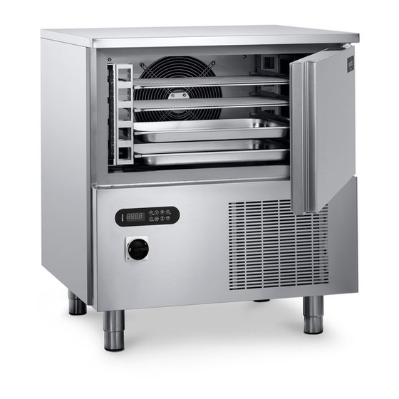
- Page 1 INSTRUCTIONS FOR USE 5-10 US TRAYS BLAST CHILLER Serie “NEW RUNNER” EVX-205 Control panel version BCB/05US BCB/10US Manual BCB US Rev00 01-2019 www.gemm-srl.com...
- Page 2 Serial Number BCB US Rev.00 01-2019 pag. 2...
- Page 3 INDEX SAFETY 1.1 – Symbols used 1.2 – General warnings 1.3 – Residual risks 1.4 – Personnel 1.5 – Improper use 1.6 – Safety devices 1.7 – Stop functions GENERAL INFORMATION 2.1 – Marking 2.2 – Declaration of conformity 2.3 – Warranty 2.4 –...
- Page 4 INSTALLATION 5.1 – Preparation for installation 5.2 – Unpacking 5.2.1 – Means required 5.2.2 – Unpacking procedure 5.3 – Handling the blast chiller 5.3.1 – Means required 5.3.2 – Handling the unpacked blast chiller 5.4 – Blast chiller assembly SETTING UP 6.1 –...
- Page 5 MAINTENANCE 8.1 – Special precautions 8.2 – Routine maintenance 8.2.1 – Routine maintenance table (tab. 5) 8.2.2 – Cleaning the chamber 8.2.3 – Cleaning the outside of the appliance 8.2.4 – Cleaning the condenser 8.2.5 – Cleaning the core probe 8.3 –...
-
Page 6: Symbols Used
1. – SAFETY 1.1 – SYMBOLS USED This symbol indicates information and warnings which if not observed could damage the appliance or compromise the safety of personnel. This symbol indicates information and warnings regarding electrical devices which if not observed could damage the appliance or compromise the safety of personnel. -
Page 7: Residual Risks
Do not expose the appliance to rain or sprays of water. Routine and extraordinary maintenance that require the electrical box to be opened or even partial dismantling of the blast chiller must be carried out only after the appliance has been disconnected. If the supply cord is damaged, it must be replaced with an identical one by the manufacturer, its service agent or similarly qualified persons in order to avoid a hazard - risk of electric shock. -
Page 8: Improper Use
1.5 – IMPROPER USE The blast chiller must not be used: − for purposes different from those given in paragraph 3.2 “Description of blast chiller and its use”; − with safety systems not working; − after badly done installation; − by untrained personnel;... -
Page 9: Safety Devices
1.6 – SAFETY DEVICES Personnel exposed to the hazards inherent in moving parts are protected by special safety devices on the appliance. − grilles covering the cooling fans (ref. 1 fig. 2); − grilles covering the condenser unit (ref. 2 fig. 2). The appliance is also provided with devices to protect the food during processing. -
Page 10: Stop Functions
1.7 – STOP FUNCTIONS The entire appliance is controlled by an electronic circuit board. The stop function is represented by the button (ref. 1 fig. 3). Whatever condition the machine is in, holding down the button for 3 seconds sets in standby the machine. Whatever condition the machine is in, switching off the main switch (ref. -
Page 11: General Information
2 – GENERAL INFORMATION Thank you for choosing a blast chiller of our production. Read this manual very carefully and make sure it is available to those who will install, use and maintain the equipment. 2.1 – MARKING The ID plates are located on the outside of the appliance, in the bottom right-hand corner of the front: Fig. 4 below shows copies. -
Page 12: Declaration Of Conformity
2.2 – DECLARATION OF CONFORMITY BCB US Rev.00 01-2019 pag. 12... -
Page 13: Warranty
2.3 – WARRANTY The warranty covering the various parts of the appliance is valid from the date on the relative delivery note and is as described in the sales agreement. The warranty does not cover damage to the appliance caused by: transport and/or handling;... - Page 14 3 – MACHINE DESCRIPTION 3.1 –TECHNICAL DATA BCB/05US Model External dimensions inches 33 7/8 X 30 3/4 X 37 3/4 Weight Trays 5 (26X18'') Max load for trays Chamber temperature °F 203 / - 40 Output 57 (+ 149 °F ÷ + 37 °F); 35 (+ 149 °F ÷ 0 °F) R404A Compressor power Max.
- Page 15 BCB/10US Model External dimensions inch 33 7/8 X 33 7/8 X 61 3/8 Weight Trays 10 (26X18'') Max load for trays Chamber temperature °F 203 / - 40 Output 75 (+ 149 °F ÷ + 37 °F); 48.5 (+ 149 °F ÷ 0 °F) R404A Compressor power 1 1/2...
-
Page 16: Main Parts
3.2 – DESCRIPTION OF BLAST CHILLER AND ITS USE Blast chillers are appliances with a powerful refrigeration system that can rapidly reduce the temperature at the core of food. Ideal for use in kitchens, bakeries and ice cream establishments. The machine’s main work cycles are CHILLING and FREEZING. -
Page 17: Ambient Conditions
3.3 – NOISE The appliance is designed and built to keep its noise level as low as possible. 3.4 –AMBIENT CONDITIONS Bakeries, confectioner’s, ice cream makers, and kitchens in general Installation site Relative humidity < 80% without condensation Climatic class 5 +104°F 40%HR Tab. -
Page 18: Transport And Handling
4 – TRANSPORT AND HANDLING 4.1 – TRANSPORT The packing used is suitable for the type, dimensions and weight of the appliance and ensures that it is protected and remains undamaged during transport and delivery to the purchaser. The blast chiller must be placed in position and kept upright on a pallet and surrounded by its packing box throughout its journey. -
Page 19: Authorized Personnel
AUTHORIZED PERSONNEL Specialised fork-lift truck operator. Individual safety devices: safety shoes; safety gloves. Personnel carrying out such operations must not wear rings, wrist watches, jewellery, loose or unfastened garments, such as, for example, ties, torn garments, scarves, unbuttoned jackets or blouses with open zips, etc. In general, personnel must wear safety apparel. -
Page 20: Preparation For Installation
5 – INSTALLATION Use the utmost care in handling the appliance, so as to avoid damage to persons or things. Do not start the appliance if there are faults on the control panel or parts are damaged. AUTHORIZED PERSONNEL Specialised electrician. Individual safety devices: −... - Page 21 5.2.2 – UNPACKING PROCEDURE All the handling and unpacking operations must be carried out with extreme care, making sure that all personnel is strictly at a safety distance and that no-one stands under suspended loads, be they still or in motion. To unpack the appliance just remove its cardboard wrapping.
-
Page 22: Electrical Connection
6 – SETTING UP AFTER INSTALLING THE APPLIANCE, WAIT AT LEAST TWO HOURS BEFORE TURNING IT ON. 6.1 – CONNECTIONS 6.1.1 – ELECTRICAL CONNECTION Electrical connection must be made by a specialised electrician. − Check that the power supply voltage given on the ID plate corresponds to that available at the installation site. - Page 23 7 – USE AFTER INSTALLING THE APPLIANCE, WAIT AT LEAST TWO HOURS BEFORE TURNING IT ON. 7.1 – USE FORSEEN Blast chillers are appliances with a powerful refrigeration system that can rapidly reduce the temperature at the core of food. Ideal for use in kitchens, bakeries and ice cream establishments. The machine’s main work cycles are CHILLING and FREEZING.
-
Page 24: Control Panel
7.3 – CONTROL PANEL Fig. 7 BCB US Rev.00 01-2019 pag. 24... - Page 25 The buttons on the control panel are as follows: With the machine OFF (0) press once to go to STANDBY (1). With the machine on STANDBY press BUTTON 0/1, once to START a cycle. When a cycle is in progress START/STOP press once to STOP it.
-
Page 26: Use Procedures
HARD BLAST Illuminated during the hard blast chilling/hard blast freezing. CHILLER/FREEZING DEFROST Illuminated during the defrost. Illuminated during the on of the accessory, as UV lamp, warmed AUXILIARY probe, where installed 7.4 – CONTROL PROCEDURES The entire appliance is controlled by an electronic circuit board. When the machine is powered the appliance display illuminates fully for a “lamp-test”... - Page 27 7.6 – SOFT CHILLING 7.6.1 – SELECTING AND SETTING OF SOFT CHILLING CYCLE Load the machine suitably with the food to be chilled, place the core probe into the food and close the door. With the appliance on STANDBY press : the display will show the set point temperature of the room referred to 23°F cycle, in the meantime the icons flash.
- Page 28 7.7 – HARD CHILLING 7.7.1 – SELECTING AND SETTING OF HARD CHILLING CYCLE Load the machine suitably with the food to be chilled, place the core probe into the food and close the door. With the appliance on STANDBY press : the display will show the set point temperature of the room referred to 23°F cycle, in the meantime the icons flash.
- Page 29 7.8 – FREEZING 7.8.1– SELECTING AND SETTING OF FREEZING CYCLE Load the machine suitably with the food to be frozen, place the core probe into the food and close the door. With the appliance on STANDBY press : the display will show the set point temperature of the room referred to - 40°F cycle, in the meantime the icons flash.
-
Page 30: Special Uses
7.9 – SPECIAL USES 7.9.1 – PRE-CHILLING FUNCTION OR CONTINUOUS CYCLE. If the temperature of the food to be chilled is very high (above 149°F) it is advisable to pre-chill it in the following way: press the button for some seconds, the device will start and the led will flash. -
Page 31: Maintenance
8 – MAINTENANCE 8.1 – SPECIAL PRECAUTIONS Contact the manufacturer for any anomalies not described in this manual; contact the manufacturer also for any doubts during the maintenance operations described herein. Maintenance carried out by unauthorized personnel may damage the appliance and expose the operator to serious hazards. Maintenance carried out by unauthorized personnel is considered tampering with the appliance and therefore nulls the warranty and relieves the manufacturer of any responsibility. - Page 32 METHOD Clean very carefully the internal part of the chamber, the door closure surface (ref. 1 fig. 8) and gasket (ref. 2 fig. 8), using a non-abrasive sponge soaked in neutral detergent. Rinse with a sponge soaked in water and dry with a clean cloth. Proper cleaning of the inside of the appliance prevents the formation of bad odour which could affect the end product negatively.
-
Page 33: Cleaning The Outside Of The Appliance
8.2.3 – CLEANING THE OUTSIDE OF THE APPLIANCE Carry out this operation whenever necessary. APPLIANCE STATUS: I/O main switch in position “O” (OFF); power supply plug disconnected from the mains. AUTHORIZED PERSONNEL Appliance operator. METHOD Clean the outer surface of the appliance (steel base and panelling), using a non-abrasive sponge soaked in neutral detergent. -
Page 34: Cleaning The Condenser
8.2.4 – CLEANING THE CONDENSER Carry out this operation every 30 days. APPLIANCE STATUS: I/O main switch in position “O” (OFF); power supply plug disconnected from the mains. AUTHORIZED PERSONNEL Appliance operator. METHOD To ensure that the appliance works properly and efficiently, the air condenser (ref. 1 fig. 9) must be kept clean so that the air can circulate freely. - Page 35 8.2.5 – CLEANING THE CORE PROBE Carry out this operation at every cycle. APPLIANCE STATUS: I/O main switch in position “O” (OFF); AUTHORIZED PERSONNEL Appliance operator. METHOD The core probe (ref. 1 fig. 10) must always be cleaned before a new cycle so as to avoid polluting the product in any way. Remove all residue by means of a sponge soaked in neutral detergent.
-
Page 36: Extraordinary Maintenance
8.3 – EXTRAORDINARY MAINTENANCE If the appliance needs extraordinary maintenance, or if operating anomalies occur that are not described in this manual, contact the manufacturer. 8.4 – OPERATING ANOMALIES AND FAULTS It is important to remember that whatever machine status is, pressing the button for 3 seconds turns it OFF and switching OFF the main switch. - Page 37 9 – DISMANTLING Contact the manufacturer to dismantle the appliance in any way. 10 – DISPOSAL 10.1 – DISPOSAL METHOD APPLIANCE STATUS electronic circuit board in position “O” (OFF); I/O main switch in position “O” (OFF); power supply plug disconnected from the mains. METHOD The appliance is made of ferrous materials, electronic components and plastics.
-
Page 38: Ordering Spare Parts
Unauthorized disposal of the product by the user is punished by the application of fines established by the countries in which the appliance is disposed of. 11 – SPARE PARTS 11.1 – ORDERING SPARE PARTS Contact the manufacturer or authorized dealer to order spare parts. 12 –... - Page 39 BCB US Rev.00 01-2019 pag. 39...
- Page 40 BCB US Rev.00 01-2019 pag. 40...
- Page 41 BCB US Rev.00 01-2019 pag. 41...
- Page 42 NOTE BCB US Rev.00 01-2019 pag. 42...
- Page 44 GEMM srl Via del Lavoro, 37 - Loc. Cimavilla - 31013 CODOGNE' (TV) - ITALY T. +39 0438 778504 – F. +39 0438 470249 e-mail: info@gemm-srl.com www.gemm-srl.com Iscr.Reg.Impr. TV - CF e P.IVA 03441880261 - REA TV 272556 Registro Prod. AEE-TV n IT08020000001108...
Need help?
Do you have a question about the New Runner Series and is the answer not in the manual?
Questions and answers
Hello. Can I get parts breakdown for M#N BCB/05 us Serial 20230711016 ?