Table of Contents
Advertisement
Available languages
Available languages
Advertisement
Table of Contents

Subscribe to Our Youtube Channel
Related Manuals for Gemm NEW RUNNER Series

Summary of Contents for Gemm NEW RUNNER Series
- Page 1 ISTRUZIONI D’USO INSTRUCTIONS FOR USE ABBATTITORE 5-10-15-24 TEGLIE 5-10-15-24 TRAYS BLAST CHILLER Serie “NEW RUNNER” EVFTFT-818 Control panel version BCT/05 BCT/10 BCT/15 BCT/24 Manual BCT - Touch Rev00 05-2015 www.gemm-srl.com...
- Page 2 BCT_T Rev.00 05-2015 pag. 2...
-
Page 3: Table Of Contents
SOMMARIO / INDEX INFORMAZIONI GENERALI GENERAL INFORMATION 1.1 – Dati di marcatura / Marking / 1.2 – Dichiarazione di conformità / Declaration of conformity 1.3 – Garanzia / Warranty 1.4 – Assistenza / After-sales service 1.5 – Utilizzo e conservazione del manuale / How to use and keep the manual 1.5.1 –... - Page 4 MESSA IN OPERA SETTING UP 6.1 – Collegamenti / Connections 6.1.1 – Collegamento elettrico / Electrical connection 6.2 – Controlli preliminari / Preliminary checks 6.2.1 – Regolazioni / Regulation 7.1 – Usi previsti / Use forseen 7.2 – Usi non previsti / Unforseen use 7.3 –...
- Page 5 MANUTENZIONE MAINTENANCE 8.1 – Precauzioni particolari / Special precautions 8.2 – Manutenzione ordinaria / Routine maintenance 8.2.1 – Tabella riassuntiva delle manutenzioni ordinarie (tab. 5)/ Routine maintenance table (tab. 5) 8.2.2 – Pulizia cella interna / Cleaning the chamber 8.2.3 – Pulizia parte esterna dell’apparecchiatura / Cleaning the outside of the appliance 8.2.4 –...
-
Page 6: Informazioni Generali
1 – INFORMAZIONI GENERALI La ringraziamo per aver scelto un nostro Abbattitore di temperatura serie TOP . Leggere con molta attenzione il presente manuale, mettendolo a disposizione del personale che dovrà installare, utilizzare ed eseguire la manutenzione dell’apparecchiatura. 1.1 – DATI DI MARCATURA All’esterno dell’apparecchiatura, sul lato destro in basso verso il fronte, sono poste le targhette di identificazione della macchina : nella Fig. - Page 7 1.2 – DICHIARAZIONE DI CONFORMITA’ BCT_T Rev.00 05-2015 pag. 7...
- Page 8 1.3 – GARANZIA La garanzia sui componenti dell’apparecchiatura, avente decorrenza dalla data riportata sulla relativa bolla di consegna, è come da contratto di vendita. Non sono compresi nella garanzia danni all’apparecchiatura causati da: trasporto e/o movimentazione; errori dell’operatore; mancata manutenzione prevista nel presente manuale; guasti e/o rotture non imputabili al malfunzionamento dell’apparecchiatura;...
- Page 9 1.6 – DESCRIZIONE DEL PERSONALE Il manuale in oggetto è rivolto sia all’operatore che ai tecnici abilitati all’installazione ed alla manutenzione dell’apparecchiatura. Gli operatori non devono eseguire operazioni riservate ai manutentori o ai tecnici specializzati. Il costruttore non risponde di danni derivati dalla mancata osservanza di questo divieto. Operatore addetto all’uso dell’apparecchiatura: Personale specializzato in grado di operare con l’apparecchiatura in condizioni normali attraverso l’uso dei comandi preposti.
-
Page 10: Descrizione Della Macchina
2 – DESCRIZIONE DELLA MACCHINA 2.1 – DATI TECNICI BCT/05 Modello Dimensioni esterne 80 x 70 x 90h Peso Capacità teglie 5 EN (cm 60 x 40) oppure 5 GN (cm 53 x 32,5) Temperatura interna cella °C + 95 / - 40 Rendimento 15 (+ 65 °C ÷... - Page 11 BCT/10 Modello Dimensioni esterne 80 x 78 x 170h Peso Capacità teglie 10 EN (cm 60 x 40) oppure 10 GN (cm 53 x 32,5) Temperatura interna cella °C + 95 / - 40 Rendimento 26 (+ 65 °C ÷ + 3 °C); 16 (+ 65 °C ÷ - 18 °C) R 404 a Potenza compressore Potenza max assorbita...
- Page 12 BCT/15 Modello Dimensioni esterne 80 x 78 x 200h Peso Capacità teglie 15 EN (cm 60 x 40) oppure 15 GN (cm 53 x 32,5) Temperatura interna cella °C + 95 / - 40 Rendimento 43 (+ 65 °C ÷ + 3 °C); 32 (+ 65 °C ÷ - 18 °C) R 404 a Potenza compressore Potenza max assorbita...
- Page 13 BCT/24 Modello Dimensioni esterne 80 x 118 x 200h Peso Capacità teglie 24 EN (cm 60 x 40) oppure 12 GN 2/1 (cm 53 x 65) Temperatura interna cella °C + 95 / - 40 Rendimento 43 (+ 65 °C ÷ + 3 °C); 32 (+ 65 °C ÷ - 18 °C) R 404 a Potenza compressore Potenza max assorbita...
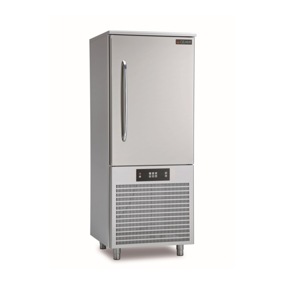
- Page 14 2.2 – DESCRIZIONE DELL’ABBATTITORE ED USO PREVISTO L’abbattitore è un’apparecchiatura con un potente sistema di refrigerazione in grado di abbassare rapidamente la temperatura al cuore degli alimenti. Il suo utilizzo è ideale in cucina, in pasticceria ed in gelateria. I principali cicli di lavoro che la macchina può effettuare sono l’abbattimento (CHILLING) e la surgelazione (FREEZING). Ciascun ciclo prevede due diverse modalità...
-
Page 15: Sicurezza
3. – SICUREZZA 3.1 – AVVERTENZE GENERALI IMPORTANTE: prima dell’utilizzo dell’apparecchiatura leggere attentamente il presente manuale d’uso e seguire scrupolosamente le istruzioni tecniche di funzionamento e le indicazioni qui contenute. L’operatore deve conoscere la posizione e le funzioni di tutti i dispositivi di controllo e le caratteristiche dell’abbattitore. - Page 16 Qualunque manomissione o sostituzione non autorizzata di una o più parti o componenti dell’apparecchiatura, l’utilizzo di accessori e materiale di consumo diversi dagli originali, possono rappresentare un rischio di incidente e sollevano il costruttore da qualunque responsabilità civile o penale. In caso di dubbio relativamente al funzionamento dell’apparecchiatura, non usarla e contattare il costruttore.
- Page 17 3.3 – DISPOSITIVI DI PROTEZIONE La protezione del personale esposto ai rischi, dovuti agli elementi mobili pericolosi, è garantita dalla presenza di opportuni dispositivi presenti sull’apparecchiatura: griglie a copertura delle ventole di raffreddamento (rif. 1 fig. 5); griglia a copertura dell’unità condensatrice (rif. 2 fig. 5). L’apparecchiatura è...
- Page 18 3.4 – FUNZIONI DI ARRESTO L' apparecchiatura nel suo complesso è controllata da una scheda elettronica. La funzione di arresto è rappresentata dal tasto (rif. 1 fig. 6). In qualsiasi stato si trovi la macchina la pressione continua per 3 secondi del tasto mette la scheda in OFF.
-
Page 19: Trasporto E Movimentazione
4 – TRASPORTO E MOVIMENTAZIONE 4.1 – TRASPORTO DELL’ABBATTITORE In funzione della tipologia e delle dimensioni e pesi sono stati utilizzati imballi adeguati a garantire l’integrità e la conservazione durante il trasporto fino alla consegna all’acquirente. L’abbattitore deve essere posizionato e mantenuto in piedi su bancale avvolto dal proprio cartone per tutta la durata del trasporto. - Page 20 PERSONALE AUTORIZZATO Tecnico specializzato mulettista. Mezzi di protezione individuali: scarpe antinfortunistiche; guanti antinfortunistici. Il personale addetto a tali operazioni non deve utilizzare anelli, orologi da polso, gioielli, capi di vestiario slacciati o sciolti, quali ad esempio cravatte, indumenti strappati, sciarpe, giacche sbottonate o bluse con chiusure a lampo aperte ecc… In generale il personale deve usare capi ad uso antinfortunistico.
-
Page 21: Installazione
5 – INSTALLAZIONE Prestare la massima cautela nel maneggiare l’apparecchiatura, in modo da evitare danni alle cose o alle persone. L’apparecchiatura non deve essere messa in funzione in caso di difetti al pannello di controllo o parti danneggiate. PERSONALE AUTORIZZATO Tecnico specializzato elettricista. - Page 22 5.2.2 – PROCEDURA DI DISIMBALLAGGIO Tutte le operazioni di movimentazione e disimballaggio devono essere effettuate con la massima cautela, controllando che tutto il personale sia rigorosamente a distanza di sicurezza, e che nessuno sosti sotto carichi sospesi, fermi o in movimento. Per disimballare l’apparecchiatura è...
- Page 23 6 – MESSA IN OPERA DOPO LA FASE DI INSTALLAZIONE DELL’APPARECCHIATURA, ATTENDERE ALMENO DUE ORE PRIMA DI PROCEDERE ALL’ACCENSIONE DELLA STESSA. 6.1 – COLLEGAMENTI 6.1.1 – COLLEGAMENTO ELETTRICO Il collegamento elettrico deve essere effettuato da un tecnico specializzato elettricista. Controllare che la tensione di alimentazione indicata sulla targhetta di identificazione corrisponda a quella disponibile sulla rete elettrica del luogo di installazione.
- Page 24 6.2.1 – REGOLAZIONI Interventi di regolazione eseguiti da personale non autorizzato possono danneggiare l’apparecchiatura ed esporre l’operatore a seri pericoli. Interventi di regolazione eseguiti da personale non autorizzato sono considerati manomissioni dell’apparecchiatura e come tali ne fanno decadere la garanzia e sollevano il costruttore da qualunque responsabilità. BCT_T Rev.00 05-2015 pag.
- Page 25 7 – USO ALLA PRIMA ACCENSIONE IL CONTROLLORE PROPONE UN’ATTESA DI 90 MINUTI “Att 90”. DURANTE QUALI L’APPARECCHIATURA ESEGUE PRE-RISCALDAMENTO COMPRESSORE. SI CONSIGLIA VIVAMENTE DI RISPETTARE I TEMPI TECNICI PROPOSTI AL FINE DI PRESERVARE FUNZIONAMENTO E DURATA DEL COMPRESSORE. 7.1 – USO PREVISTO L’abbattitore è...
- Page 26 7.4 – INTERFACCIA UTENTE 7.4.1 – CENNI PRELIMINARI Esistono i seguenti stati di funzionamento: lo stato “off” (il dispositivo non è alimentato) lo stato “stand-by” (il dispositivo è alimentato ed è spento) lo stato “on” (il dispositivo è alimentato, è acceso ed è in attesa dell’avvio di un ciclo di funzionamento) lo stato “run”...
- Page 27 Premere e rilasciare il tasto ON / STAND-BY (1). Se la durata dell’interruzione dell’alimentazione è stata tale da provocare l’errore orologio (codice “rtc”), sarà necessario impostare nuovamente il giorno e l’ora reale; si veda il paragrafo 11.1 “Impostazione del giorno e dell’ora reale”.
- Page 28 Durante lo stato “run” il dispositivo visualizzerà: se è in corso un abbattimento a temperatura o una surgelazione a temperatura, la temperatura rilevata dalla sonda ad ago, la temperatura della cella, il nome del programma (se previsto) e il tempo trascorso dall’avvio dell’abbattimento o della surgelazione se è...
- Page 29 Premere e rilasciare il tasto (4), quindi premere e rilasciare ripetutamente il tasto (5) o il tasto (6) per selezionare l’ingresso o l’uscita. Per uscire dalla procedura operare nel modo seguente: Premere e rilasciare il tasto ESCAPE o non operare per 60 s. 7.4.6 –...
- Page 30 7.4.7 – ATTIVAZIONE SBRINAMENTO IN MODO MANUALE Blocco / sblocco della tastiera Per bloccare la tastiera operare nel modo seguente: Assicurarsi che il parametro E8 sia impostato a 1 e che non sia in corso alcuna procedura. Premere e rilasciare il tasto ON / STAND-BY (1), quindi premere e rilasciare il tasto interattivo più in alto a sinistra (2).
- Page 31 7.5 – FUNZIONAMENTO 7.5.1 – CENNI PRELIMINARI Il dispositivo è in grado di gestire i seguenti tipi di cicli di funzionamento: abbattimento a temperatura e conservazione abbattimento hard a temperatura e conservazione abbattimento a tempo e conservazione abbattimento hard a tempo e conservazione abbattimento continuo surgelazione a temperatura e conservazione surgelazione soft a temperatura e conservazione...
- Page 32 7.5.3 – ABBATTIMENTO A TEMPERATURA E CONSERVAZIONE Abbattimento a temperatura e conservazione Il ciclo di abbattimento a temperatura e conservazione è diviso nelle seguenti due fasi: abbattimento conservazione. Alla conclusione di una fase il dispositivo passa automaticamente alla successiva. Per avviare il ciclo operare nel modo indicato: Assicurarsi che il dispositivo sia nello stato “on”.
- Page 33 Per interrompere il ciclo operare nel modo indicato: Tenere premuto il tasto START / STOP per 3 s. I successivi parametri stabiliscono i seguenti valori: il parametro r3 stabilisce la temperatura di fine abbattimento il parametro r5 stabilisce la durata massima dell’abbattimento il parametro r7 stabilisce il setpoint di lavoro durante l’abbattimento.
- Page 34 7.5.4 – ABBATTIMENTO HARD A TEMPERATURA E CONSERVAZIONE Abbattimento hard a temperatura e conservazione Il ciclo di abbattimento hard a temperatura e conservazione è diviso nelle seguenti tre fasi: fase hard dell’abbattimento abbattimento conservazione. Alla conclusione di una fase il dispositivo passa automaticamente alla successiva. Per avviare il ciclo operare nel modo indicato: Assicurarsi che il dispositivo sia nello stato “on”.
- Page 35 Per interrompere il ciclo operare nel modo indicato: Tenere premuto il tasto START / STOP per 3 s. I successivi parametri stabiliscono i seguenti valori: il parametro r5 stabilisce la durata massima dell’abbattimento il parametro r9 stabilisce il setpoint di lavoro durante la fase hard dell’abbattimento il parametro r13 stabilisce la temperatura di fine della fase hard dell’abbattimento.
- Page 36 7.5.5 – ABBATTIMENTO A TEMPO E CONSERVAZIONE Abbattimento a tempo e conservazione Il ciclo di abbattimento a tempo e conservazione è diviso nelle seguenti due fasi: abbattimento conservazione. Alla conclusione di una fase il dispositivo passa automaticamente alla successiva. Per avviare il ciclo operare nel modo indicato: Assicurarsi che il dispositivo sia nello stato “on”.
- Page 37 Per interrompere il ciclo operare nel modo indicato: Tenere premuto il tasto START / STOP per 3 s. I successivi parametri stabiliscono i seguenti valori: il parametro r1 stabilisce la durata dell’abbattimento il parametro r7 stabilisce il setpoint di lavoro durante l’abbattimento. Trascorsa la durata dell’abbattimento il dispositivo passa automaticamente alla conservazione e il buzzer viene attivato per il tempo stabilito con il parametro AA.
- Page 38 Premere e rilasciare il tasto MENÙ, quindi premere e rilasciare il tasto o il tasto per selezionare la durata dell’abbattimento e il setpoint di lavoro durante l’abbattimento. Premere e rilasciare il tasto o il tasto per modificare questi valori, quindi il tasto ESCAPE per memorizzarli; è...
- Page 39 7.5.7 – ABBATTIMENTO CONTINUO Abbattimento continuo Per avviare il ciclo operare nel modo indicato: Assicurarsi che il dispositivo sia nello stato “on”. Assicurarsi che la tastiera non sia bloccata e che non sia in corso alcuna procedura. Premere e rilasciare il tasto (1), premere e rilasciare il tasto (2), quindi premere e rilasciare due volte il (3): il dispositivo visualizzerà...
- Page 40 7.5.8 – SURGELAZIONE A TEMPERATURA E CONSERVAZIONE Surgelazione a temperatura e conservazione Il ciclo di surgelazione a temperatura e conservazione è diviso nelle seguenti due fasi: surgelazione conservazione. Alla conclusione di una fase il dispositivo passa automaticamente alla successiva. Per avviare il ciclo operare nel modo indicato: Assicurarsi che il dispositivo sia nello stato “on”.
- Page 41 Per interrompere il ciclo operare nel modo indicato: Tenere premuto il tasto START / STOP per 3 s. I successivi parametri stabiliscono i seguenti valori: il parametro r4 stabilisce la temperatura di fine surgelazione il parametro r6 stabilisce la durata massima della surgelazione il parametro r8 stabilisce il setpoint di lavoro durante la surgelazione.
- Page 42 7.5.9 – SURGELAZIONE A TEMPO E CONSERVAZIONE Il ciclo di surgelazione a tempo e conservazione è diviso nelle seguenti due fasi: surgelazione conservazione. Alla conclusione di una fase il dispositivo passa automaticamente alla successiva. Per avviare il ciclo operare nel modo indicato: Assicurarsi che il dispositivo sia nello stato “on”.
- Page 43 Trascorsa la durata della surgelazione il dispositivo passa automaticamente alla conservazione e il buzzer viene attivato per il tempo stabilito con il parametro AA. Per tacitare il buzzer premere e rilasciare un tasto. Durante la surgelazione il dispositivo visualizza la temperatura della cella, il nome del programma (se previsto) e la durata della surgelazione.
- Page 44 7.6.2 – DEFROST Operare nel modo seguente: Assicurarsi che il dispositivo sia nello stato “on”, che sia in corso un preraffreddamento o una conservazione. Assicurarsi che la tastiera non sia bloccata e che non sia in corso alcuna procedura. Premere e rilasciare il tasto (1), premere e rilasciare il tasto (2), quindi premere e rilasciare il tasto START / STOP (3).
- Page 45 Per uscire dalla procedura operare nel modo seguente: Premere e rilasciare il tasto ESCAPE o non operare per 60 s. Il ventilatore viene acceso alla velocità selezionata trascorsi 5 s dal rilascio del tasto o del tasto 7.6.4 – TEST PER LA VERIFICA DEL CORRETTO INSERIMENTO SONDA AD AGO Se la sonda ad ago è...
- Page 46 7.6.6 – RISCALDAMENTO SONDA AD AGO Heating the needle probe Operare nel modo seguente: Assicurarsi che il dispositivo sia nello stato “on” o che sia in corso una conservazione e che la porta sia aperta, ovvero che l’ingresso micro porta sia attivo. Assicurarsi che la tastiera non sia bloccata e che non sia in corso alcuna procedura.
- Page 47 Premere e rilasciare il tasto o il tasto per selezionare questi valori e premere e rilasciare il tasto o il tasto per modificarli. Premere e rilasciare il tasto START / STOP (1): verrà avviato il test per la verifica del corretto inserimento della sonda ad ago;...
- Page 48 7.7 – ALTRE FUNZIONI 7.7.1 – MEMORIZZAZIONE DI UN PROGRAMMA Operare nel modo seguente: Assicurarsi che la tastiera non sia bloccata e che non sia in corso alcuna procedura. Premere e rilasciare il tasto (1) prima di avviare un ciclo di funzionamento o durante una conservazione: il dispositivo visualizzerà...
- Page 49 Premere e rilasciare il tasto (1) o il tasto (2) per selezionare il numero del programma, quindi premere e rilasciare il tasto (3) per associargli un nome. Premere e rilasciare il tasto , il tasto , il tasto o il tasto per selezionare il carattere, quindi premere e rilasciare il tasto per confermarlo.
- Page 50 Premere e rilasciare il tasto (4), quindi premere e rilasciare il tasto (5) o il tasto (6) per selezionare l’allarme (maggiore è il numero che segue il codice dell’allarme e più vecchio è l’allarme). : il dispositivo visualizzerà le informazioni relative all’allarme. Premere e rilasciare il tasto per visualizzare le informazioni dell’allarme precedente o dell’allarme Premere e rilasciare il tasto...
- Page 51 per impostare “149”, quindi premere e rilasciare il tasto Premere e rilasciare ripetutamente il tasto Per uscire dalla procedura operare nel modo seguente: Premere e rilasciare il tasto ESCAPE o non operare per 60 s. 7.7.5 – VISUALIZZAZIONE DELLE ORE FUNZIONAMENTO COMPRESSORE Display of compressor operating hours Operare nel modo seguente: Assicurarsi che lo strumento sia nello stato “on”.
- Page 52 Per uscire dalla procedura operare nel modo seguente: Premere e rilasciare il tasto ESCAPE o non operare per 60 s. Per cancellare le ore di funzionamento del compressore si veda il paragrafo 11.3.5 “Ripristino delle impostazioni di fabbrica”. 7.7.6 – IMPOSTAZIONE DEL GIORNO E DELL’ORA REALE Setting the real date and time Operare nel modo seguente: Assicurarsi che lo strumento sia nello stato “on”.
- Page 53 7.7.7 – IMPOSTAZIONE DEI PARAMETRI DI CONFIGURAZIONE Setting the configuration parameters Operare nel modo seguente: Assicurarsi che lo strumento sia nello stato “on”. Assicurarsi che la tastiera non sia bloccata e che non sia in corso alcuna procedura. Premere e rilasciare il tasto HOME (1), premere e rilasciare il tasto MENÙ (2), quindi premere e rilasciare (3) per selezionare “PARAMETRI”.
- Page 54 7.7.8 – CANCELLAZIONE PROGRAMMI Restoring the factory setting Operare nel modo seguente: Accedere alla procedura; si veda il paragrafo 11.3.1 “Accesso alla procedura”. (1) per selezionare “Programmi”, premere e rilasciare ripetutamente il tasto Premere e rilasciare il tasto per impostare “149”, quindi premere e rilasciare il tasto (3).
- Page 55 7.7.10 – CANCELLAZIONE DELLE ORE DI FUNZIONAMENTO DEL COMPRESSORE Operare nel modo seguente: Accedere alla procedura; si veda il paragrafo 11.3.1 “Accesso alla procedura”. (1) per selezionare “rCH”, premere e rilasciare ripetutamente il tasto Premere e rilasciare ripetutamente il tasto (2) per impostare “149”, quindi premere e rilasciare il tasto (3).
- Page 56 Per eseguire l’upload dei parametri di configurazione operare nel modo indicato: Assicurarsi che il dispositivo sia nello stato “stand-by”. Inserire una periferica USB nella porta seriale USB; assicurarsi che la periferica contenga il documento di testo di nome “param.txt” (si veda il punto 3). (1) per selezionare “UPLOAD PARAMETRI”, quindi premere e rilasciare il tasto Premere e rilasciare il tasto (2): verrà...
- Page 57 Alla conclusione del download rimuovere la periferica USB dalla porta seriale USB. Per eseguire l’upload dei programmi operare nel modo indicato: Assicurarsi che il dispositivo sia nello stato “stand-by”. Inserire una periferica USB nella porta seriale USB; assicurarsi che la periferica contenga il documento di testo di nome “ricette.txt”...
- Page 58 7.7.13 – DOWNLOAD DELLE INFORMAZIONI RELATIVE AGLI ALLARMI HACCP Per eseguire il download delle informazioni relative agli allarmi HACCP operare nel modo indicato: Assicurarsi che il dispositivo sia nello stato “stand-by”. Inserire una periferica USB nella porta seriale USB. (3) per impostare il giorno e l’ora dalla quale le Premere e rilasciare il tasto (1), il tasto (2) o il tasto...
- Page 59 Premere e rilasciare il tasto (4), quindi premere e rilasciare il tasto (5) per selezionare “SETUP REGISTRAZIONI”. Premere e rilasciare il tasto , premere e rilasciare il tasto o il tasto per selezionare l’informazione, quindi premere e rilasciare il tasto (o il tasto ) per aggiungerla (o rimuoverla).
- Page 60 8 – MANUTENZIONE 8.1 – PRECAUZIONI PARTICOLARI Il costruttore deve essere contattato per qualunque anomalia non descritta nel presente manuale; il costruttore deve essere contattato anche per qualsiasi dubbio riscontrato durante le operazioni di manutenzione qui descritte. Interventi di manutenzione eseguiti da personale non autorizzato possono danneggiare l’apparecchiatura ed esporre l’operatore a seri pericoli.
- Page 61 8.2.2 – PULIZIA CELLA INTERNA Questa operazione deve essere effettuata secondo necessità. STATO DELL’APPARECCHIATURA: pulsante di accensione/spegnimento in posizione OFF ( sul display); spina di alimentazione scollegata dalle rete elettrica. PERSONALE AUTORIZZATO Operatore addetto all’uso dell’apparecchiatura. MODALITA’ Pulire con estrema cura la parte interna della cella, la superficie di chiusura della porta (rif. 1 fig. 8) e la guarnizione (rif. 2 fig.
- Page 62 8.2.3 – PULIZIA PARTE ESTERNA DELL’APPARECCHIATURA Questa operazione deve essere effettuata secondo necessità. STATO DELL’APPARECCHIATURA: pulsante di accensione/spegnimento in posizione OFF ( sul display); spina di alimentazione scollegata dalle rete elettrica. PERSONALE AUTORIZZATO Operatore addetto all’uso dell’apparecchiatura. MODALITA’ Pulire le superfici esterne dell’apparecchiatura (porta piano e pannellature in acciaio), utilizzando una spugna imbevuta di detergente neutro, entrambi non abrasivi.
- Page 63 8.2.4 – PULIZIA CONDENSATORE APPARECCHIATURA Questa operazione deve essere effettuata ogni 30 gg. STATO DELL’APPARECCHIATURA: pulsante di accensione/spegnimento in posizione “O” (OFF); spina di alimentazione scollegata dalle rete elettrica. PERSONALE AUTORIZZATO Operatore addetto all’uso dell’apparecchiatura. MODALITA’ Per un corretto ed efficiente funzionamento dell’apparecchiatura, è necessario che il condensatore ad aria (rif. 1 fig. 9) sia mantenuto pulito per permettere la libera circolazione dell’aria.
- Page 64 8.2.5 – PULIZIA DELLA SONDA A SPILLONE Questa operazione deve essere effettuata ad ogni ciclo. STATO DELL’APPARECCHIATURA: pulsante di accensione/spegnimento in posizione “O” (OFF); PERSONALE AUTORIZZATO Operatore addetto all’uso dell’apparecchiatura. MODALITA’ Prima di un nuovo ciclo, al fine di evitare qualsiasi tipo di “inquinamento” del prodotto, è necessario procedere alla pulizia della sonda a spillone (rif.
- Page 65 8.3 – MANUTENZIONE STRAORDINARIA Nel caso in cui l’apparecchiatura necessitasse di interventi di manutenzione straordinaria, o nel caso in cui riportasse delle anomalie di funzionamento non trattate nel presente manuale, contattare il costruttore. 8.4 – SEGNALI E INDICAZIONI La seguente tabella illustra il significato dei LED di segnalazione. Significato LED abbattimento.
- Page 66 LED conservazione. Se è acceso: sarà in corso una conservazione. Se lampeggia: sarà in corso la modifica del setpoint di lavoro (temperatura della cella). Barre LED intensità di abbattimento / di surgelazione (solo se il parametro F0 è impostato a 3). Forniscono informazioni relative alla velocità...
- Page 67 La seguente tabella illustra il significato dei codici di indicazione. Codice Significato È in corso uno sbrinamento. La tastiera è bloccata; si veda il paragrafo 5.7 “Blocco / sblocco della tastiera”. La tastiera è stata sbloccata; si veda il paragrafo 5.7 “Blocco / sblocco della tastiera”. 8.4.1–...
- Page 68 Allarme bassa pressione. Rimedi: verificare le condizioni dell’ingresso bassa pressione verificare il valore del parametro i8. Principali conseguenze: il compressore e il ventilatore dell’evaporatore verranno spenti l’uscita di allarme verrà attivata. Allarme protezione termica compressore. Rimedi: verificare le condizioni dell’ingresso protezione termica compressore verificare il valore del parametro i10.
- Page 69 8.4.2– ERRORI La seguente tabella illustra il significato dei codici di errore. Codice Significato Errore sonda cella. Rimedi: verificare il valore del parametro P0 verificare l’integrità della sonda verificare il collegamento dispositivo-sonda verificare la temperatura della cella. Principali conseguenze: se l’errore si manifesta durante lo stato “stand-by”, non sarà consentito nè selezionare nè avviare alcun ciclo di funzionamento se l’errore si manifesta durante l’abbattimento o la surgelazione, il ciclo verrà...
- Page 70 Errore sonda ad ago 1. Rimedi: gli stessi dell’errore sonda cella (codice “Pr1”) ma relativamente alla sonda ad ago 1. Principali conseguenze se il parametro P3 è impostato a 1: se l’errore si manifesta durante lo stato “stand-by”, i cicli di funzionamento a temperatura verranno avviati a tempo se l’errore si manifesta durante l’abbattimento a temperatura, l’abbattimento durerà...
- Page 71 9 – SMONTAGGIO Per qualsiasi attività di smontaggio dell’apparecchiatura contattare l’installatore. 10 – SMANTELLAMENTO 10.1 – MODALITA’ DI SMANTELLAMENTO STATO DELL’APPARECCHIATURA scheda elettronica posizione “O” (OFF); spina di alimentazione scollegata della rete elettrica. MODALITA’ L’apparecchiatura è costruita con materiali ferrosi, componenti elettronici e materie plastiche. Nel caso sia necessario procedere alla rottamazione, separare i diversi componenti in base al materiale di cui sono costituiti, in modo da semplificare lo smaltimento differenziato o un’eventuale riutilizzo delle parti.
- Page 72 11 – RICAMBI 11.1 – MODALITA’ DI RICHIESTA DEI RICAMBI Per la richiesta di parti di ricambio contattare il costruttore o il rivenditore autorizzato. 12 – ALLEGATI Seguono in allegato a corredo dell’apparecchiatura: Dichiarazione di conformità Schema elettrico Resoconto collaudo elettrico Valutazione vuoto, verifica perdite e carica gas impianto frigorifero.
-
Page 73: General Information
1 – GENERAL INFORMATION Thank you for choosing a blast chiller of our production. Read this manual very carefully and make sure it is available to those who will install, use and maintain the equipment. 1.1 – MARKING The ID plates are located on the outside of the appliance, in the bottom right-hand corner of the front: Fig. 1 below shows copies. -
Page 74: Dichiarazione Di Conformità / Declaration Of Conformity
1.2 – DECLARATION OF CONFORMITY BCT_T Rev.00 05-2015 pag. 74... -
Page 75: Assistenza / After-Sales Service
1.3 – WARRANTY The warranty covering the various parts of the appliance is valid from the date on the relative delivery note and is as described in the sales agreement. The warranty does not cover damage to the appliance caused by: transport and/or handling;... - Page 76 1.6 – PERSONNEL This manual is for the use of operators, authorized fitters and maintenance engineers. Operators must not carry out operations reserved for maintenance engineers or specialised technicians. The manufacturer accepts no responsibility for damage deriving from failure to observe this rule. Appliance operator: specialised person who can operate the appliance in normal working conditions by using the relevant controls.
-
Page 77: Machine Description
2 – MACHINE DESCRIPTION 2.1 –TECHNICAL DATA Model BCT/05 80 x 70 x 90h External dimensions Weight 5 EN (cm 60 x 40) or 5 GN (cm 53 x 32,5) Trays °C + 95 / - 40 Chamber temperature 15 (+ 65 °C ÷ + 3 °C); 9 (+ 65 °C ÷ - 18 °C) Output R 404 a 1,25... - Page 78 BCT/10 Model 80 x 78 x 170h External dimensions Weight 10 EN (cm 60 x 40) or 10 GN (cm 53 x 32,5) Trays + 95 / - 40 Chamber temperature °C 26 (+ 65 °C ÷ + 3 °C); 16 (+ 65 °C ÷ - 18 °C) Output R 404 a Compressor power...
- Page 79 BCT/15 Model 80 x 78 x 200h External dimensions Weight 15 EN (cm 60 x 40) or 15 GN (cm 53 x 32,5) Trays °C + 95 / - 40 Chamber temperature 43 (+ 65 °C ÷ + 3 °C); 32 (+ 65 °C ÷ - 18 °C) Output R 404 a Compressor power...
- Page 80 BCT/24 Model 80 x 118 x 200h External dimensions Weight 24 EN (cm 60 x 40) or 12 GN 2/1 (cm 53 x 65) Trays °C + 95 / - 40 Chamber temperature 43 (+ 65 °C ÷ + 3 °C); 32 (+ 65 °C ÷ - 18 °C) Output R 404 a Compressor power...
-
Page 81: Componenti Principali / Main Parts
2.2 – DESCRIPTION OF BLAST CHILLER AND ITS USE Blast chillers are appliances with a powerful refrigeration system that can rapidly reduce the temperature at the core of food. Ideal for use in kitchens, bakeries and ice cream establishments. The machine’s main work cycles are CHILLING and FREEZING. -
Page 82: Safety
3. – SAFETY 3.1 – GENERAL WARNINGS IMPORTANT: before using the appliance read this manual carefully and follow the technical operating instructions and indications to the letter. The operator must know the position and function of all the control devices and the characteristics of the blast chiller. The blast chiller complies with current safety regulations, but improper use may cause damage to persons and things. -
Page 83: Controindicazioni D'uso / Improper Use
3.2. – IMPROPER USE The blast chiller must not be used: for purposes different from those given in paragraph 2.2 “Description of blast chiller and its use”; with safety systems not working; after badly done installation; by untrained personnel;... -
Page 84: Dispositivi Di Protezione / Safety Devices
3.3 – SAFETY DEVICES Personnel exposed to the hazards inherent in moving parts are protected by special safety devices on the appliance. grilles covering the cooling fans (ref. 1 fig. 5); grilles covering the condenser unit (ref. 2 fig. 5). The appliance is also provided with devices to protect the food during processing. -
Page 85: Transport And Handling
4 – TRANSPORT AND HANDLING 4.1 – TRANSPORT The packing used is suitable for the type, dimensions and weight of the appliance and ensures that it is protected and remains undamaged during transport and delivery to the purchaser. The blast chiller must be placed in position and kept upright on a pallet and surrounded by its packing box throughout its journey. - Page 86 4.2.1 – WEIGHT AND DIMENSIONS Model BCT/05 BCT/10 BCT/15 BCT/24 Dimensions 80x70x90h 80x78x200h 80x78x200h 80x118x200h Weight Tab.3 4.2.2 – MEANS REQUIRED To lift the appliance use a fork-lift truck of suitable minimum capacity. The use of unsuitable equipment can cause accidents to those involved in the operation and/or damage to the appliance.
-
Page 87: Installation
5 – INSTALLATION Use the utmost care in handling the appliance, so as to avoid damage to persons or things. Do not start the appliance if there are faults on the control panel or parts are damaged. AUTHORIZED PERSONNEL Specialised electrician. Individual safety devices: ... -
Page 88: Procedura Di Disimballaggio / Unpacking Procedure
5.2.2 – UNPACKING PROCEDURE All the handling and unpacking operations must be carried out with extreme care, making sure that all personnel is strictly at a safety distance and that no-one stands under suspended loads, be they still or in motion. To unpack the appliance just remove its cardboard wrapping. - Page 89 6 – SETTING UP AFTER INSTALLING THE APPLIANCE, WAIT AT LEAST TWO HOURS BEFORE TURNING IT ON. 6.1 – CONNECTIONS 6.1.1 – ELECTRICAL CONNECTION Electrical connection must be made by a specialised electrician. Check that the power supply voltage given on the ID plate corresponds to that available at the installation site.
- Page 90 7 – USE AFTER INSTALLING THE APPLIANCE, WAIT AT LEAST TWO HOURS BEFORE TURNING IT ON. 7.1 – USE FORSEEN Blast chillers are appliances with a powerful refrigeration system that can rapidly reduce the temperature at the core of food. Ideal for use in kitchens, bakeries and ice cream establishments. The machine’s main work cycles are CHILLING and FREEZING.
- Page 91 7.4 – USER INTERFACE 7.4.1 – FOREWORD Foreword The following operating status exist: the “off” status (the device is not powered) the “stand-by” status (the device is powered and is off) the “on” status (the device is powered, is on and is in stand-by for the start-up of an operating cycle) the “run”...
- Page 92 Press and release the ON/STAND-BY (1) key. If the duration of the power cut has been such to cause the clock error (“rtc” code), the real day and time will have to be reset; see paragraph 10.1 “Setting the real day and time”. 7.4.3 –...
- Page 93 During the "run" state the device will display: if a temperature-controlled blast chilling or deep freezing operation is in progress, the temperature detected by the needle probe, the temperature of the cabinet, the name of the program, (if envisioned) and the time passed from the start of blast chilling or deep freezing.
- Page 94 Press and release the key (4) and then repeatedly press and release the key (5) or the key (6) to select the input or the output. Operate as follows to exit the procedure: Press and release the ESCAPE key or do not operate for 60 s. 7.4.6 –...
- Page 95 7.4.7 – LOCKING / UNLOCKING OF KEYBORD Locking/unlocking of the keyboard Operate as follows to lock the keyboard: Make sure parameter E8 is set to 1 and no procedures are in progress. Press and release the ON/STAND-BY key (1) and then press the highest interactive key on the left (2). If parameter E8 is set to 2, on expiry of 60 s the keybord will automatically lock.
- Page 96 7.5 – OPERATION 7.5.1 – FOREWORD The device can manage the following operating cycles: temperature-controlled blast chilling and storage temperature-controlled hard blast chilling and storage time-controlled blast chilling and storage time-controlled hard blast chilling and storage continuous blast chilling temperature-controlled deep freezing and storage temperature-controlled soft deep freezing and storage time-controlled deep freezing and storage time-controlled soft deep freezing and storage...
- Page 97 7.5.3 – TEMPERATURE – CONTROLLED BLAST CHILLING AND STORAGE Temperature-controlled blast chilling and storage The temperature-controlled blast chilling and storage cycle is divided into the following two phases: blast chilling storage. On conclusion of a phase, the device passes automatically to the next. Operate as indicated to start the cycle: Make sure the device is in the "on"...
- Page 98 Operate as indicated to stop the cycle: Press and hold the START/STOP key 3 s. The successive parameters establish the following values: parameter r3 establishes the blast chilling end temperature parameter r5 establishes the maximum blast chilling duration parameter r7 establishes the work set-point during blast chilling. If the temperature detected by the needle probe reaches the blast chilling end temperature within the maximum blast chilling duration, it means that blast chilling has been completed successfully, the device will automatically pass to storage and the buzzer will be activated for the period of time established with parameter AA.
- Page 99 On conclusion of a phase, the device passes automatically to the next. Operate as indicated to start the cycle: Make sure the device is in the "on" status. Make sure that the keyboard is not locked and that no procedure is in progress. Press and release the key (1), press and release the key (2) and then press and release the...
- Page 100 When the temperature detected by the needle probe reaches the hard blast chilling phase end temperature, the device automatically passes to blast chilling mode. During blast chilling the device displays the temperature detected by the needle probe, the cabinet temperature, the program name (if envisioned) and the time passed since the start of blast chilling.
- Page 101 7.5.5 – TIME – CONTROLLED BLAST CHILLING AND STORAGE The time-controlled blast chilling and storage cycle is divided into the following two phases: blast chilling storage. On conclusion of a phase, the device passes automatically to the next. Operate as indicated to start the cycle: Make sure the device is in the "on"...
- Page 102 On expiry of the blast chilling duration, the device automatically passes to storage mode and the buzzer is activated for the time period established with parameter AA. Press and release a key to silence the buzzer. During storage the device displays the temperature of the cabinet, the program name (if envisioned) and the duration of blast chilling.
- Page 103 During hard blast chilling the device displays the residual blast chilling time, the temperature of the cabinet, the name of the program (if envisioned) and the time passed from the start of blast chilling. Operate as indicated to stop the cycle: Press and hold the START/STOP key 3 s.
- Page 104 7.5.7 – CONTINUOUS BLAST CHILLING Continuous blast chilling Operate as indicated to start the cycle: Make sure the device is in the "on" status. Make sure that the keyboard is not locked and that no procedure is in progress. Press and release the key (1), press and release the key (2) and then press and release the key (3)
- Page 105 Operate as indicated to start the cycle: Make sure the device is in the "on" status. Make sure that the keyboard is not locked and that no procedure is in progress. Press and release the key (1), press and release the key (2) and then press and release the key (3) and finally press and release the...
- Page 106 If the temperature detected by the needle probe reaches the deep freezing end temperature within the maximum deep freezing duration, it means that deep freezing has been completed successfully, the device will automatically pass to storage and the buzzer will be activated for the period of time established with parameter AA. Press and release a key to silence the buzzer.
- Page 107 Press and release the MENU key and then press and release the key or the key to select the deep freezing duration and the work set-point during deep freezing. Press and release the key or the key to modify these values and then the ESCAPE key to memorise them; these values can also be memorised through parameters r2 and r8.
- Page 108 Time-controlled soft deep freezing and storage 7.6 –SPECIAL FUNCTIONS AND USES 7.6.1 – PRE – COOLING START - UP. Every operating cycle can be preceded by pre-cooling. Operate as indicated to start pre-cooling: Make sure the device is in the "on" status. Make sure that the keyboard is not locked and that no procedure is in progress.
- Page 109 7.6.3 – SELECTING THE EVAPORATOR FAN SPEED Operate as follows: Make sure the device is in the "on" status. Make sure that the keyboard is not locked and that no procedure is in progress. Press and release the key (1), press and release the key (2) and then press and release the key (3) or key (4).
- Page 110 7.6.5 – SWICHING ON UV LIGHT FOR THE STERILISATION CYCLE Switching on UV light for sterilisation cycle Operate as follows: Make sure that parameter u11 is set at 2. Make sure the device is in the "on" status and that the door is closed, i.e. the door micro switch is not active. Make sure that the keyboard is not locked and that no procedure is in progress.
- Page 111 7.6.7 – FISH SANIFICATION The fish sanification cycle is divided into the following three phases: blast chilling maintenance storage. On conclusion of a phase, the device passes automatically to the next. Operate as indicated to start the cycle: Make sure the device is in the "on" status. Make sure that the keyboard is not locked and that no procedure is in progress.
- Page 112 Operate as indicated to stop the cycle: Press and hold the START/STOP key 3 s. When the temperature detected by the needle probe reaches the blast chilling end temperature, it means that blast chilling has been completed and the device will automatically pass to maintenance. During maintenance the the blast chilling end temperature also establishes the work set-point during maintenance.
- Page 113 Press and release the key (1) or the key (2) to select the program number and then press and release the key (3) in order to associate a name. Press and release the key, the key, the key or the key to select the character and then press and release the key to confirm it.
- Page 114 Press and release the key (4) and then press and release the key (5) or the key (6) to select the alarm (the greater the number that follows the alarm code, the older the alarm). Press and release the key: the device will display the information relative to the alarm. Press and release the key or the key to display the information of the previous alarm or the successive...
- Page 115 key to set “149” and then press and release the Repeatedly press and release the key. Operate as follows to exit the procedure: Press and release the ESCAPE key or do not operate for 60 s. 7.7.5 – DISPLAY OF COMPRESSOR OPERATING HOURS Display of compressor operating hours Operate as follows: Make sure that the instrument is in the “on”...
- Page 116 7.7.6 – SETTING THE REAL DATE AND TIME Setting the real date and time Operate as follows: Make sure that the instrument is in the “on” status. Make sure that the keyboard is not locked and that no procedure is in progress. Press and release the HOME key (1) and then press and release the MENU key (2).
- Page 117 key (5) to set “-19”and then press and Press and release the key (4), repeatedly press and release the release the key (6) again. Operate as follows to select a parameter: Press and release the key or the key. Operate as follows to set a parameter: Press and release the key or the key.
- Page 118 7.7.9 – DELETING FAVOURITES Operate as follows: Access to the; see paragraph 10.3.1 “Access to the procedure”. key (1) to select “Programs”, repeatedly press and release the key (2) to set “149” Press and release the and then press and release the key (3).
- Page 119 7.7.11 – UPLOAD AND DOWNLOAD OF THE CONFIGURATION PARAMETERS Upload and download of the configuration parameters To make the download of the configuration parameters operate as follows: Make sure the device is in the “stand-by” status. Insert an USB peripheral in the USB serial port. key (1) to select “DOWNLOAD PARAMETERS”, then press and release the Press and release the key (2):...
- Page 120 To the end of the upload remove the USB peripheral from the USB port. 7.7.12 – UPLOAD AND DOWNLOAD OF THE PROGRAMS Upload and download of the programs To make the download of the programs operate as follows: Make sure the device is in the “stand-by” status. Insert an USB peripheral in the USB serial port.
- Page 121 key (1) to select “UPLOAD PROGRAMS”, then press and release the Press and release the key (2): it will automatically be started the reading (from the peripheral) of the text document by name “ricette.txt” (containing information about the programs); the reading procedure can take some minutes. To the end of the download remove the USB peripheral from the USB port.
- Page 122 To set the kind of information to be downloadedoperate as follows: Make sure the device is in the “on” status. Make sure the keyboard is not locked and no procedure is in progress. Press and release the HOME key (1), press and release the MENU key (2), then press and release key (3) to select “HACCP ALARMS”.
- Page 123 To the end of the download remove the USB peripheral from the USB port. To delete the information relative to the HACCP alarms see paragraph 7.7.3 “Deleting the information relative to the HACCP alarms”. BCT_T Rev.00 05-2015 pag. 123...
- Page 124 8 – MAINTENANCE 8.1 – SPECIAL PRECAUTIONS Contact the manufacturer for any anomalies not described in this manual; contact the manufacturer also for any doubts during the maintenance operations described herein. Maintenance carried out by unauthorized personnel may damage the appliance and expose the operator to serious hazards. Maintenance carried out by unauthorized personnel is considered tampering with the appliance and therefore nulls the warranty and relieves the manufacturer of any responsibility.
- Page 125 METHOD Clean very carefully the internal part of the chamber, the door closure surface (ref. 1 fig. 8) and gasket (ref. 2 fig. 8), using a non-abrasive sponge soaked in neutral detergent. Rinse with a sponge soaked in water and dry with a clean cloth.
- Page 126 8.2.3 – CLEANING THE OUTSIDE OF THE APPLIANCE Carry out this operation whenever necessary. APPLIANCE STATUS: ON/OFF button on OFF ( on the display); power supply plug disconnected from the mains. AUTHORIZED PERSONNEL Appliance operator. METHOD Clean the outer surface of the appliance (steel base and panelling), using a non-abrasive sponge soaked in neutral detergent.
- Page 127 8.2.4 – CLEANING THE CONDENSER Carry out this operation every 30 days. APPLIANCE STATUS: ON/OFF button on OFF ( on the display); power supply plug disconnected from the mains. AUTHORIZED PERSONNEL Appliance operator. METHOD To ensure that the appliance works properly and efficiently, the air condenser (ref. 1 fig. 9) must be kept clean so that the air can circulate freely.
- Page 128 8.2.5 – CLEANING THE CORE PROBE Carry out this operation at every cycle. APPLIANCE STATUS: ON/OFF button in position “O” (OFF); AUTHORIZED PERSONNEL Appliance operator. METHOD The core probe (ref. 1 fig. 10) must always be cleaned before a new cycle so as to avoid polluting the product in any way.
- Page 129 8.3 – EXTRAORDINARY MAINTENANCE If the appliance needs extraordinary maintenance, or if operating anomalies occur that are not described in this manual, contact the manufacturer. 8.4 – SIGNALS AND INDICATIONS The following table illustrates the meaning of the signalling LEDS. Meaning Blast chilling LED.
- Page 130 Storage LED. If it is on: storage will be in progress. If flashing: work set-point modification will be in progress (cabinet temperature). Blast chilling/deep freezing intensity LED bars (only if parameter F0 is set at 3). They supply information relative to evaporator fan speed (for example, one bar on corresponds to speed 1, two bars on correspond to speed 2, three bars on correspond to speed 3, etc.).
- Page 131 The following table illustrates the meaning of the indication codes. Code Meaning Defrosting will be in progress. The keyboard is locked, see paragraph 5.10 "Lock/unlock the keyboard". The keyboard has been locked, see paragraph 5.10 "Lock/unlock the keyboard". 8.4.1– ALARMS The following table illustrates the meaning of the alarm codes.
- Page 132 High pressure alarm. Solutions: check the conditions of the high pressure input check the value of parameters i5 and i6. Main consequences: the effect established with parameter i5 the alarm output will be activated. Low pressure alarm. Solutions: check the conditions of the low pressure input check the value of the parameter i8.
- Page 133 8.4.2– ERRORS The following table illustrates the meaning of the error codes. Code Meaning Cabinet probe error. Solutions: check the value of the parameter P0 check the integrity of the probe check the device-probe connection check the temperature of the cabinet. Main consequences: if the error occurs during the “stand-by”...
- Page 134 Needle probe error 1. Solutions: the same as the cabinet probe error (“Pr1” code) but relative to the needle probe 1. ain consequences if parameter P3 is set at 1: if the error occurs during the “stand-by” status, temperature-controlled operating cycles will be started by time-control if the error occurs during temperature-controlled blast chilling, this will have duration of the time set by parameter r1...
- Page 135 9 – DISMANTLING Contact the manufacturer to dismantle the appliance in any way. 10 – DISPOSAL 10.1 – DISPOSAL METHOD APPLIANCE STATUS electronic circuit board in position “O” (OFF); power supply plug disconnected from the mains. METHOD The appliance is made of ferrous materials, electronic components and plastics. If it needs to be disposed of, separate the various components according to the material of which they are made, to simplify separate waste collection or re-use of the parts.
- Page 136 11 – SPARE PARTS 11.1 – ORDERING SPARE PARTS Contact the manufacturer or authorized dealer to order spare parts. 12 – APPENDICES The appliance comes with the following appendices: Declaration of conformity Electrical diagram Electrical approval report Assessment of vacuum, leakage and gas loading for cooling unit. BCT_T Rev.00 05-2015 pag.
- Page 137 BCT_T Rev.00 05-2015 pag. 137...
- Page 138 BCT_T Rev.00 05-2015 pag. 138...
Need help?
Do you have a question about the NEW RUNNER Series and is the answer not in the manual?
Questions and answers