
Related Manuals for Woodward easYlite-100


Summary of Contents for Woodward easYlite-100
- Page 1 37481A easYlite-100 Annunciator Manual Software Version 1.0006 or higher Manual 37481A...
- Page 2 Provides other helpful information that does not fall under the warning or caution categories. Woodward reserves the right to update any portion of this publication at any time. Information provided by Woodward is believed to be correct and reliable. However, Woodward assumes no responsibility unless otherwise expressly undertaken.
-
Page 3: Table Of Contents
Manual 37481A easYlite-100 - Annunciator Revision History Rev. Date Editor Change NEW 10-05-05 Release based on Manual 37307; External IKD mode and ToolKit support added 10-06-29 Minor changes Content 1. G ..................6 HAPTER ENERAL NFORMATION Related Documents ..........................Overview ..............................7 Applications .............................. - Page 4 Install ToolKit Configuration Files ....................26 Starting ToolKit Software ......................27 Configure ToolKit Software ......................28 Connect ToolKit and the easYlite-100 Unit ................. 29 View easYlite-100 Data with ToolKit ................... 31 Configure the easYlite-100 with ToolKit ..................32 System Management ..........................33 Password System ........................
- Page 5 Table 9-6: Configuration settings for one easYlite-100 and one easYgen-1000 - transmission parameters ......47 Table 9-7: Configuration settings for one easYlite-100 and one easYgen-2000 / easYgen-3000 - transmission parameters ..47 Table 9-8: Configuration settings for two easYlite-100 and one easYgen - bus parameters ............. 48 Table 9-9: Configuration settings for two easYlite-100 and one easYgen-1000 - transmission parameters ......
-
Page 6: Chapter 1. General Information
Table 1-1: Manual - overview Please refer to the easYgen-1000 Series, easYgen-2000 Series or easYgen-3000 Series documentation for further information about the configuration of the easYlite-100. All manuals can be downloaded from the Woodward Publications Server: http://www.woodward.com/pubs/pubpage.cfm Page 6/64 © Woodward... -
Page 7: Overview
The easYlite-100 annunciator is able to display warning, alarm or status messages of a Woodward genset control remotely (for example in a remote control station). The easYlite-100 operates in two different modes (internal mode & external IKD mode) to support a wide variety of easYgen devices. -
Page 8: Applications
Manual 37481A easYlite-100 - Annunciator Applications ≡≡≡≡≡≡≡≡≡≡≡≡≡≡≡≡≡≡≡≡≡≡≡≡≡ Figure 1-2: Applications overview Page 8/64 © Woodward... -
Page 9: Expansions - External Ikd Mode
Manual 37481A easYlite-100 - Annunciator Expansions - External IKD mode ≡≡≡≡≡≡≡≡≡≡≡≡≡≡≡≡≡≡≡≡≡≡≡≡≡ Figure 1-3: Expansions - external IKD mode © Woodward Page 9/64... -
Page 10: Chapter 2. Electrostatic Discharge Awareness
CAUTION To prevent damage to electronic components caused by improper handling, read and observe the pre- cautions in Woodward manual 82715, Guide for Handling and Protection of Electronic Controls, Printed Circuit Boards, and Modules. Page 10/64 © Woodward... -
Page 11: Chapter 3. Housing
Manual 37481A easYlite-100 - Annunciator Chapter 3. Housing Dimensions / Panel Cut-Out ≡≡≡≡≡≡≡≡≡≡≡≡≡≡≡≡≡≡≡≡≡≡≡≡≡ Figure 3-1: Housing - panel cut-out Description Dimension Tolerance Height Total 158 mm Panel cut-out 138 mm + 1.0 mm Housing dimension 136 mm Width Total 158 mm... -
Page 12: Installation
Manual 37481A easYlite-100 - Annunciator Installation ≡≡≡≡≡≡≡≡≡≡≡≡≡≡≡≡≡≡≡≡≡≡≡≡≡ For installation into a door panel, proceed as follows: Panel cut-out Cut out the panel according to the dimensions in Figure 3-1. Remove terminals Loosen the wire connection terminal screws on the back of the unit and remove the wire connection terminal strip if required (1). -
Page 13: Chapter 4. Wiring Diagram
The DPC must be connected with this port. Relay 1 (Horn) 12/24 Vdc Internal 1 MOhm RC element 2,000 V Shield CAN-H CAN bus CAN-L Subject to technical mocifications. 2005-05-09 | easYlite-100 Wiring Diagram eYl100ww-0519-ap.skf Figure 4-1: Wiring diagram - easYlite-100 © Woodward Page 13/64... -
Page 14: Chapter 5. Connections
0.05 0.38 600MCM 0.08 750MCM 0.14 0.75 300MCM 1000MCM 0.25 350MCM 0.34 500MCM Table 5-1: Conversion chart - wire size Terminal Arrangement ≡≡≡≡≡≡≡≡≡≡≡≡≡≡≡≡≡≡≡≡≡≡≡≡≡ terminal strip configuration port Figure 5-1: easYlite-100 back view - terminal arrangement Page 14/64 © Woodward... -
Page 15: Power Supply
For a proper operation of the device, a minimum initial voltage of 10.5 Vdc is necessary when switching on the easYlite-100. After this, a continuous operating voltage between 6.5 and 32.0 Vdc is possible to operate the easYlite-100 safely. The unit is capable of handling voltage drops to 0 V for a maximum of 10 ms. Relay Output ≡≡≡≡≡≡≡≡≡≡≡≡≡≡≡≡≡≡≡≡≡≡≡≡≡... -
Page 16: Interfaces
Manual 37481A easYlite-100 - Annunciator Interfaces ≡≡≡≡≡≡≡≡≡≡≡≡≡≡≡≡≡≡≡≡≡≡≡≡≡ Overview Figure 5-4: Interfaces - overview No. Connection from ... to ... easYlite-100 [DPC connector] PC [COM-Port] PIN 1 -------------------------------- PIN 4 (connect with PIN 8) PIN 2 -------------------------------- PIN 3 PIN 3... -
Page 17: Can Bus
Manual 37481A easYlite-100 - Annunciator CAN Bus Wiring CAN-L CAN-H Figure 5-5: Interfaces - CAN bus Terminal Description CAN-L 2.5 mm² CAN bus CAN-H 2.5 mm² Shield 2.5 mm² Table 5-5: CAN bus - terminal assignment Shielding Shield CAN-L CAN-H... -
Page 18: Chapter 6. Operation
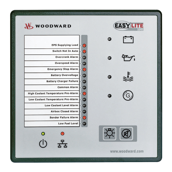
Manual 37481A easYlite-100 - Annunciator Chapter 6. Operation Front Panel ≡≡≡≡≡≡≡≡≡≡≡≡≡≡≡≡≡≡≡≡≡≡≡≡≡ Figure 6-1: Front panel Figure 6-1 illustrates the front panel which includes push-buttons and LEDs. A short description of the front pan- el is given below. LEDs The LEDs indicate operating states of the unit and alarm messages. -
Page 19: Operation And Display
Manual 37481A easYlite-100 - Annunciator Operation and Display ≡≡≡≡≡≡≡≡≡≡≡≡≡≡≡≡≡≡≡≡≡≡≡≡≡ The easYlite-100 offers two operation modes: easYlite-100 Internal mode External IKD mode easYgen-1000 Series easYgen-1000 Series easYgen-2000 Series easYgen-3000 Series Software Version Software Version 1.0000 or higher 3.1000 or higher 1.0006 or higher 1.1500 or higher... -
Page 20: Internal Mode
- Annunciator Internal Mode Function of the Status LEDs The easYlite-100 has several status LEDs to indicate the operating state. The LEDs indicate the following condi- tions: LEDs 14 configurable alarm, warning, and status LEDs (red), configurable in the easYlite-100. -
Page 21: External Ikd Mode
- Annunciator External IKD Mode In the External IKD mode the easYlite-100 has a behavior like an IKD terminal of Woodward. It listens to partic- ular CAN-IDs which originally are sent for the IKD1 and the IKD2. In this mode the LEDs and the relay output are directly driven by the easYgen genset control. -
Page 22: Chapter 7. Functional Description
- up to 4 easYlite-100 can be connected to an easYgen-3000 (Software Version 1.1500 or higher) via CAN bus. Furthermore, the easYlite-100 allows to connect a signaling device like a horn via relay 1. The signaling device indicates an alarm issue at the genset and/or a failure of the CAN connection between easYlite-100 and genset control. -
Page 23: Led Test
LED Test ≡≡≡≡≡≡≡≡≡≡≡≡≡≡≡≡≡≡≡≡≡≡≡≡≡ A test of the easYlite-100 LEDs may be performed by pressing button . All LEDs must be illuminated in the color indicated on page 20 (Internal mode) & 21 (External IKD mode) while this button is pressed. The bicolor CAN bus status LED must be illuminated yellow (green + red) when it is functioning correctly. -
Page 24: Function Of The Pre-Assigned Leds (Internal Mode Only)
(Internal mode only) ≡≡≡≡≡≡≡≡≡≡≡≡≡≡≡≡≡≡≡≡≡≡≡≡≡ When the easYlite-100 is configured to internal mode, four LEDs are pre-assigned. These LEDs must be confi- gured correctly to indicate the intended warning, alarm or status message, which is transmitted from the con- nected easYgen genset control via the CAN bus. It is not possible to use general standard values since the confi- guration depends on the individual wiring of the genset control. -
Page 25: Chapter 8. Configuration Easylite-100
≡≡≡≡≡≡≡≡≡≡≡≡≡≡≡≡≡≡≡≡≡≡≡≡≡ Install ToolKit Configuration and Visualization Software NOTE Woodward’s ToolKit software is required to configure the unit via PC. ToolKit Version 3.4.1 or higher Install ToolKit Software Please insert the enclosed Product CD in the CD-ROM drive of your computer The CD is going to start automatically (autostart function needs to be activated) Please go to the section “Software”... -
Page 26: Install Toolkit Configuration Files
Manual 37481A easYlite-100 - Annunciator Install ToolKit Configuration Files Please insert the enclosed Product CD in the CD-ROM drive of your computer The CD is going to start automatically (autostart function needs to be activated) Please go to the section “Configuration Files” and follow the instructions described there Alternatively ToolKit configuration files can be downloaded from our Website. -
Page 27: Starting Toolkit Software
- Annunciator Starting ToolKit Software Start ToolKit via Windows Start menu -> Programs ->Woodward -> ToolKit 3.x Please press the button “Open Tool” Go to the “Application” folder and open then the folder equal to the part number (P/N) of your device (e.g. -
Page 28: Configure Toolkit Software
Manual 37481A easYlite-100 - Annunciator Configure ToolKit Software Start the configuration by using the toolbar. Please go to Tools -> Options The options window will be displayed Adjust the default locations of the configuration files The displayed language can be selected here The changes become effective after clicking “OK”... -
Page 29: Connect Toolkit And The Easylite-100 Unit
PC does not have a serial port to connect the null modem cable to, use a USB to serial adapter. Open ToolKit via Windows Start menu -> Programs -> Woodward -> ToolKit 3.x From the main ToolKit window, click File then select “Open Tool”..., or click the Open Tool icon on the tool bar. - Page 30 Manual 37481A easYlite-100 - Annunciator NOTE Depending on the computer used and the installed operation system, problems with the communica- tion via an infrared connection may occur. NOTE If your computer is equipped with a Bluetooth interface please deactivate it temporarily in the Windows system control menu in the case that ToolKit is freezing building up a connection.
-
Page 31: View Easylite-100 Data With Toolkit
Manual 37481A easYlite-100 - Annunciator View easYlite-100 Data with ToolKit The following figure shows an example visualization screen of ToolKit: Figure 8-1: ToolKit - visualization screen Navigation through the various visualization and configuration screens is performed by clicking on icons, by selecting a navigation button (e.g. -
Page 32: Configure The Easylite-100 With Toolkit
Manual 37481A easYlite-100 - Annunciator Configure the easYlite-100 with ToolKit The following figure shows an example configuration screen of ToolKit: Figure 8-3: ToolKit - configuration screen Entering a new value or selecting a value from a defined list will change the value in a field. The new value is written to the controller memory by changing to a new field or pressing the Enter key. -
Page 33: System Management
Manual 37481A easYlite-100 - Annunciator System Management ≡≡≡≡≡≡≡≡≡≡≡≡≡≡≡≡≡≡≡≡≡≡≡≡≡ The following is a description of the easYlite-100 parameters. Note that these parameters may only be viewed and/or changed through ToolKit. Password System Figure 8-4: Password system Actual code level display only This value displays the code level which is currently selected. - Page 34 Manual 37481A easYlite-100 - Annunciator NOTE The following passwords are valid for all access possibilities (via serial RS-232 (DPC) interface. The passwords can be used for the access control systems of the different configuration access methods. Commissioning level code 0000 to 9999 The password for the commissioning code level is configured here.
-
Page 35: Factory Settings
Manual 37481A easYlite-100 - Annunciator Factory Settings It may be desirable to configure the easYlite-100 from a known state if the unit has been previously configured for another application. Restoring factory default settings can be accomplished easily. Factory settings YES/NO This parameter enables the easYlite-100 to have the factory default setting restored. -
Page 36: Home Page
Manual 37481A easYlite-100 - Annunciator Home Page ≡≡≡≡≡≡≡≡≡≡≡≡≡≡≡≡≡≡≡≡≡≡≡≡≡ The easYlite-100 offers two operation modes: easYlite-100 Internal mode External IKD mode easYgen-1000 Series easYgen-1000 Series easYgen-2000 Series easYgen-3000 Series Software Version Software Version 1.0000 or higher 3.1000 or higher 1.0006 or higher 1.1500 or higher... -
Page 37: Application Of Leds - Internal Mode
Manual 37481A easYlite-100 - Annunciator Application of LEDs - Internal Mode Display alarm LED [x] one message from list One warning/alarm/status message from the message list in Table 8-2 can be assigned to the alarm LED [x] here. The LED [x] will be illuminated if the assigned warning/alarm/status is detected. -
Page 38: Table 8-2: Configurable Warning/Alarm/Status Messages
Manual 37481A easYlite-100 - Annunciator Warning/alarm/status message Description CANopen Fault Various alarm bits of the genset CAN-Fault J1939 Digital input 1 Digital input 2 Digital input 3 Digital input 4 Alarm messages triggered by discrete inputs Digital input 5 at the genset... -
Page 39: Application Of Leds - External Ikd Mode
Manual 37481A easYlite-100 - Annunciator Application of LEDs - External IKD Mode Display LED [x] external digital outputs from easYgen Directly configured (via easYgen) LEDs as IKD1 relay 1 to 8 and IKD2 relay1 to 8. The LED [x] will be il- luminated if the assigned digital output is detected. -
Page 40: Application Of The Relay 1
If the relay is configured to "Horn" or "CAN fail or horn“, relay 1 will be energized with any occurring genset alarm regardless whether the alarm is assigned to an easYlite-100 LED or not. It is recommend- ed to assign the configurable alarm message "Horn" to one of the easYlite-100 LEDs to prevent an... -
Page 41: Configure Can Interface
Manual 37481A easYlite-100 - Annunciator Configure CAN Interface ≡≡≡≡≡≡≡≡≡≡≡≡≡≡≡≡≡≡≡≡≡≡≡≡≡ Device number 1 to 128 A unique address is assigned to the control though this parameter. This unique address permits the controller to be correctly identified on the CAN bus. The address assigned to the controller may only be used once. All other bus addresses are calculated on the number entered in this parameter. -
Page 42: Internal And External Ikd Mode
1 to 99 The maximum answer time of external devices is configured here. If the acknowledge message of the easYlite-100 is not replied within this time, it will be repeated. NOTE Refer to easYgen “Interface Manual” for detailed information about the configuration of the easYlite- 100 and the connected genset controller. -
Page 43: Version
This is the serial number of the easYlite-100 and identifies the unit. Boot item number display only This is the item number of the firmware, which is stored on the easYlite-100. Boot revision display only This is the revision of the firmware, which is stored on the easYlite-100. -
Page 44: Chapter 9. Configuration Easygen Series
After a correct CAN bus connection between the easYlite-100 and the easYgen has been established and the same baud rate has been configured, the CAN bus status LED at the easYlite-100 flashes green four times to in- dicate the missing PDOs. -
Page 45: Table 9-4: Configuration Settings For Easylite-100 And Easygen-1000 - Transmission Parameters
- Annunciator If the above settings have been configured correctly, the easYlite-100 CAN bus status LED will illuminate green. The CAN bus status LED does not indicate whether the data transmitted with the PDO is correct. It only indicates that a PDO is received. -
Page 46: External Ikd Mode
125 kBd CANopen Master Producer Heartbeat Time 2000 ms 2000 ms COB-ID SYNC Message 80 hex Table 9-5: Configuration settings for one easYlite-100 and one easYgen - bus parameters Data Transmission Settings One easYgen-1000 and one easYlite-100: easYgen-1000 easYlite-100 Parameter Parameter... -
Page 47: Table 9-6: Configuration Settings For One Easylite-100 And One Easygen-1000 - Transmission Parameters
9614 Event-timer 20ms 8963 Selected Data Protocol 65001 9619 Number of Mapped Objects Transmit PDO3 9620 COB-ID 8000 0000h Switched off Table 9-7: Configuration settings for one easYlite-100 and one easYgen-2000 / easYgen-3000 - transmission parameters © Woodward Page 47/64... -
Page 48: One Easygen And Two Easylite-100
Producer Heartbeat Time 2000 ms 2000 ms 2000 ms COB-ID SYNC Message 80 hex Table 9-8: Configuration settings for two easYlite-100 and one easYgen - bus parameters Data Transmission Settings One easYgen-1000 and two easYlite-100: easYgen-1000 1. easYlite-100 2. easYlite-100... -
Page 49: Table 9-9: Configuration Settings For Two Easylite-100 And One Easygen-1000 - Transmission Parameters
COB-ID 0000h Transmit PDO4 8000 Switched 9630 COB-ID 0000h Table 9-9: Configuration settings for two easYlite-100 and one easYgen-1000 - transmission parameters One easYgen-2000 / easYgen-3000 and two easYlite-100: easYgen-2000 / easYgen-3000 1. easYlite-100 2. easYlite-100 Para- Para- Para- meter... -
Page 50: Table 9-10: Configuration Settings For Two Easylite-100 And One Easygen-2000 / Easygen-3000 - Transmission Parameters
Transmission Type 9614 Event-timer 20ms Selected Data 8963 65001 Protocol Number of 9619 Mapped Objects Transmit PDO3 8000 Switched 9620 COB-ID 0000h Table 9-10: Configuration settings for two easYlite-100 and one easYgen-2000 / easYgen-3000 - transmission parameters Page 50/64 © Woodward... -
Page 51: Chapter 10. Technical Data
Manual 37481A easYlite-100 - Annunciator Chapter 10. Technical Data Name plate ------------------------------------------------------------------------------------------------------ Serial number (numerical) Serial number (Barcode) Date of production (YYMM) Item number Item revision number Details Technical data Type Unit name Type Extended description UL sign (Example for a typical name plate) Ambient variables --------------------------------------------------------------------------------------------- Power supply ................ - Page 52 Manual 37481A easYlite-100 - Annunciator Housing --------------------------------------------------------------------------------------------------------- Type ..................Woodward easYpack 158x158 Dimensions (W × H × D) ...............158 × 158 × 40 mm Front cutout (W × H) ............... 138 [+1.0] × 138 [+1.0] mm Connection ..............screw and plug terminals 2.5 mm²...
-
Page 53: Appendix A. Common
- Annunciator Appendix A. Common Alarm Classes ≡≡≡≡≡≡≡≡≡≡≡≡≡≡≡≡≡≡≡≡≡≡≡≡≡ The easYlite-100 does not generate alarms. It only displays alarms generated by the easYgen genset control. The easYgen distinguishes between the following alarm classes: Alarm class Visible in the display LED "Alarm"... -
Page 54: Appendix B. Front Customization
Appendix B. Front Customization The easYlite-100 is designed to be adapted to any desired language and can be customized to your demands using a paper strip. The paper strip is intended for labeling the configurable LEDs. The paper strip is divided into 14 lines, one for each LED. You can customize the paper strip to reflect the warn- ing/alarm/status message configured to the respective LED in the desired language. -
Page 55: Appendix C. Protocol 65000, 65001 For External Ikd Mode
Bit 6 = 1: set LED 18 Bit 7 = 1: set LED 19 CANopen TPDO 1 is sent by the easYlite-100 to the easYgen. It there is received as protocol 65000 / 65001 / 65002 / 65003 TPDO 1 Byte 0... -
Page 56: Appendix D. Troubleshooting
Appendix D. Troubleshooting If problems are encountered while commissioning or operating the easYlite-100, please refer to the troubleshoot- ing table below and ToolKit prior to contacting Woodward for technical assistance. The most common problems and their solutions are described in the troubleshooting table. If problems are encountered between the easYlite- 100 and its wiring and the engine or other devices, refer to the respective manuals for solving the problem. -
Page 57: Appendix E. List Of Parameters
Manual 37481A easYlite-100 - Annunciator Appendix E. List of Parameters Unit number P/N _____________________________ Rev _______________________________ Version easYlite- ______________________________________________________________ Project _____________________________________________________________________ Serial number S/N _______________ Date ______________________________ Parameter Setting range Default value Customer setting MAIN MENU Internal Internal Internal easYlite LED mode Ext. - Page 58 Manual 37481A easYlite-100 - Annunciator SYSTEM CODES Code level CAN port Info Code level serial port / DPC Info Commissioning level code 0000 to 9999 0003 Temp. commissioning level 0000 to 9999 0200 code Factory settings YES / NO YES / NO ...
-
Page 59: Appendix F. Service Options
≡≡≡≡≡≡≡≡≡≡≡≡≡≡≡≡≡≡≡≡≡≡≡≡≡ If a control (or any part of an electronic control) is to be returned to Woodward for repair, please contact Wood- ward in advance to obtain a Return Authorization Number. When shipping the unit(s), attach a tag with the fol- lowing information: •... -
Page 60: Packing A Control
Stuttgart [+49 (0) 711 789 54-0]. They will help expedite the processing of your order through our distributors or local service facility. To expedite the repair process, contact Woodward in advance to obtain a Return Authoriza- tion Number, and arrange for issue of a purchase order for the unit(s) to be repaired. No work can be started until a purchase order is received. -
Page 61: How To Contact Woodward
+49 (0) 711 789 54-100 e-mail: stgt-info@woodward.com For assistance outside Germany, call one of the following international Woodward facilities to obtain the address and phone number of the facility nearest your location where you will be able to get information and service. Facility... -
Page 62: Engineering Services
- Annunciator Engineering Services ≡≡≡≡≡≡≡≡≡≡≡≡≡≡≡≡≡≡≡≡≡≡≡≡≡ Woodward Industrial Controls Engineering Services offers the following after-sales support for Woodward prod- ucts. For these services, you can contact us by telephone, by e-mail, or through the Woodward website. • Technical support •... -
Page 63: Technical Assistance
Manual 37481A easYlite-100 - Annunciator Technical Assistance ≡≡≡≡≡≡≡≡≡≡≡≡≡≡≡≡≡≡≡≡≡≡≡≡≡ If you need to telephone for technical assistance, you will need to provide the following information. Please write it down here before phoning: Contact Your company ____________________________________________________ Your name _______________________________________________________ Phone number ____________________________________________________... - Page 64 Phone +49 (0) 711 789 54-0 • Fax +49 (0) 711 789 54-100 stgt-info@woodward.com Homepage http://www.woodward.com/power Woodward has company-owned plants, subsidiaries, and branches, as well as authorized distributors and other authorized service and sales facilities throughout the world. Complete address/phone/fax/e-mail information for all locations is available on our website (www.woodward.com).
Need help?
Do you have a question about the easYlite-100 and is the answer not in the manual?
Questions and answers