
Related Manuals for Decatur Electronics Genesis II Select


Summary of Contents for Decatur Electronics Genesis II Select
- Page 1 Genesis II ™ Select User’s Manual & Installation Guide Canada Variant Revision 16/September/2015 Copyright 2009, 2015 Decatur Electronics, Inc.
- Page 3 Genesis II ™ Select User’s Manual & Installation Guide Canada Variant Revision 16/September/2015...
-
Page 4: Table Of Contents
Operating the Genesis II Select™ ........ - Page 5 6.5 Moving Mode Same Direction ........39 6.5.1 Setting Separation Speed .
-
Page 6: Welcome To Decatur Electronics
Welcome to Decatur Electronics, Inc. Thank you for choosing the Decatur Electronics Genesis II Select™ — A highly advanced traffic radar unit that will reward your department with years of dependable service. The Genesis II Select™ design incorporates high performance and long range, with many leading features. -
Page 7: Genesis Ii Select™ Features
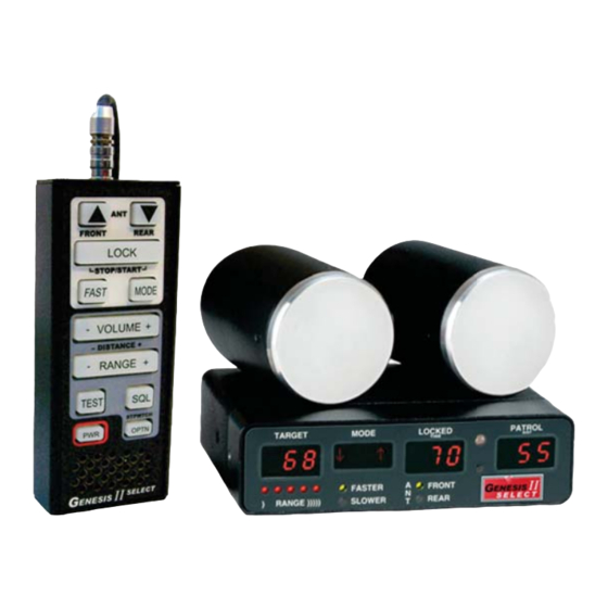
Genesis II Select™ Features The Genesis II Select™ is a highly advanced traffic radar device offering many advanced capabilities. It includes 32-bit digital signal processing (DSP), a versatile detachable computer/display unit, a variety of interchangeable antennas, and an easy-to-use hand-held remote control. -
Page 8: About This Manual
About This Manual This manual contains valuable information to help you set up, use and maintain your Genesis II Select™, so you can optimize its life and keep it at peak performance. Please take a moment to read through it, and keep it handy for future reference. - Page 9 Your Genesis II Select™ radar unit includes selections from the following components: Detachable Computer/ Handheld Remote Display Unit Various Connector Cables K and Ka Band Antennas Various Mounting Brackets Optional VIP Optional Radar Mirror Display 16/September/2015...
-
Page 10: Quick Start
1. Quick Start Use the following instructions to quick start your Genesis II Select™: 1. With all cables, antennas and the hand remote attached, plug the cigar plug of the radar into a powered 12VDC cigarette lighter receptacle in the patrol motor vehicle. -
Page 11: Installation
2. Installation Use the following instructions to mount your Genesis II Select™: 2.1 Separating the Computer/Display Unit (optional) If the space in your motor vehicle is at a premium, you will appreciate Genesis II Select’s™ compact size and versatile components. You can separate and remotely mount the computer unit from the display unit. -
Page 12: Mounting And Connecting The Computer/Display Unit
Then attach and secure the connectors with the thumbscrews on the sides of each cable connector. Figure 2.1c Secure the connecting cable by fastening the thumbscrews into the standoffs. To return the unit to a one-piece configuration, remove the cables and standoffs, line up the 9-pin connectors, and push the two pieces together. - Page 13 You can mount the computer/display unit behind and to the side of the steering wheel or on the dashboard. The computer unit easily withstands and remains accurate in temperature extremes. Dash- mounting the unit promotes safety; you can read the display without taking your eyes off the road.
- Page 14 1. Align the red dot on the connector with the red dot at the top of the receptacle. 2. Push the connector into the receptacle until you hear a click. Figure 2.2b Align the red dot on the connector with the red dot on the computer receptacle.
- Page 15 Serial connector On the back of the computer unit there is a female DB-9 connector marked “serial” that allows you to connect the Genesis II Select™ to other devices (i.e. display signs, in-car video, PCs). To use this RS232 serial connector you will need a communications cable. (A communications cable for video and PC is not included.
-
Page 16: Mounting And Connecting The Antenna
2.3 Mounting and Connecting the Antenna Three different antenna types are available for the Genesis II Select™ : K-band, K-band Directional, and Ka-band silver ring. These antennas are incredibly strong, yet compact and lightweight. The antennas are interchangeable, so you can configure your radar unit with a second antenna of the same or different band without changing the hardware, software, and controls. - Page 17 Front Antenna Mounting When mounting the front antenna bracket to the windshield use the following bullet points to help in determining the proper location. Do Not mount the antenna in the deployment path of the air bag or where it will obstruct the driver's vision.
- Page 18 Antenna Alignment After you affix the bracket, adjust the position of the antenna. ANY SIGNIFICANT DEVIATION FROM A PARALLEL ORIENTATION CAN AFFECT THE RADAR’S READING DUE TO THE COSINE EFFECT. Figure 2.3e Figure 2.3f Correct Orientation Incorrect Orientation The antenna is parallel to the target The antenna and target vehicle's vehicle's direction.
-
Page 19: Installation Check
After you install the components, for safety, double-check to ensure all components are secure. 2.5 VIP Installation (Optional) If your Genesis II Select has come with the optional Motor vehicle Interface Portal™ (VIP™) then use the following installation instructions. WARNING including the motor vehicle and radar are powered off. -
Page 20: Connecting To The On-Board Diagnostic Port
2.5.2 Connecting to the On-Board Diagnostic Port Connect the VIP™ to the motor vehicle’s On Board Diagnostics port. (Refer to your owner’s manual for the location of your motor vehicle's OBD-II port.) In some motor vehicles the clearance between where the diagnostics port is located and the bottom of the dash is very close and can cause the port and VIP™... -
Page 21: Vip™ Activation
2.5.4 VIP™ Activation Before activating the VIP™ it is recommended that you read the section on Operating the Genesis II Select™. The patrol motor vehicle must be running, simply having the key turned to auxiliary is not enough to fully activate the VIP™. Make sure the LED light on the VIP™... -
Page 22: Configuring The Vip
2.5.5 Configuring the VIP™ To get the Genesis II Select™ to recognize that the VIP™ has been connected it may be necessary to go into the radar’s menu feature and select the VIP™. -
Page 23: Computer/Display Unit
3. Computer/Display Unit The Genesis II Select™ faceplate contains four windows for displaying the patrol, target, locked target speeds and mode. In addition, the faceplate also has indicators used to show the range setting, faster or slower setting and whether the front or rear antenna has been selected. -
Page 24: Lights
LOCKED: When you press the LOCK button, the LOCKED window holds and displays the target speed that was in the TARGET window. PATROL: Displays the patrol speed. The window is blank when the radar unit is in Stationary Mode or when the motor vehicle is traveling below the minimum patrol speed. -
Page 25: Moving Mode Same Direction Using Directional Antenna
FASTER: When a target motor vehicle is moving faster than the patrol motor vehicle press the FAST button so the Faster light illuminates. Figure 3.2.2.1 The Faster light 3.2.2.2 Moving Mode Same Direction using Directional Antennas When using directional antennas in the same direction mode once the directional antenna has been selected the FASTER and SLOWER lights will go out and pressing the FAST button will no longer be used to select FASTER or SLOWER since the selection will... -
Page 26: Fastest Target [Opt]
3.2.2.4 Fastest Target [OPT] A variation of the Faster Target is available as an option. This option works the same as the Faster Target feature except the unit stays in FASTER Mode until the FAST button is pressed again. In other words, if your unit is equipped with this option then the FASTER light will remain illuminated when the FASTER button is pressed and the strongest target speed will be displayed in the TARGET... -
Page 27: Hand-Held Remote Control
4. Hand-Held Remote Control Figure 4a The S778-41CC-0 hand held remote keypad controls. Figure 4b The S778-41CC-0 hand-held remote control unit with detachable cable. until the remote is plugged back in. 16/September/2015... -
Page 28: Control Buttons
The Genesis II Select™ will, as long as the antenna remains activated, continue to track both the speed of the target in the target window and the patrol motor vehicle speed in the patrol window . - Page 29 SQUELCH (SQL): Selects the type of Doppler audio you hear. In squelch mode, the sound is only the Doppler tone for the currently displayed target. In the unsquelched mode, the unit sends out all Doppler tones received by the antenna—patrol motor vehicles, targets, interference, and noise.
- Page 30 MENU FEATURE (TEST/OPTN): The menu feature allows the operator to fine tune some of the settings of the radar. To activate the menu feature, press and hold the TEST button down until "MENU" is displayed in the mode window. Pressing OPTN steps through the menu items and the antenna buttons change the settings.
-
Page 31: Communication System Controls
6.2 Front and Rear Antenna At power up, the Genesis II Select™ antennas are in standby mode. (Standby mode is when the antenna is not transmitting.) If no antenna is connected to the unit, the FRONT and REAR lights cycle on... - Page 32 When the FRONT light illuminates, the FRONT antenna is transmitting. To discontinue transmitting (to place the radar back into standby mode), press the same (ANT) button. The Genesis II Select™ has three main operating modes: Stationary, Moving Mode Opposite Direction, and Moving Mode Same Direction. 16/September/2015...
-
Page 33: Stationary Mode
6.3 Stationary Mode You can use Stationary Mode to monitor traffic that is moving toward or away from the parked patrol motor vehicle. Figure 6.3 Tracking a target vehicle with a parked patrol vehicle and the radar in Stationary Mode. 6.3.1 Using Non-Directional Antennas When using non-directional antennas, to switch to Stationary Mode, press and hold the MODE button for two seconds. -
Page 34: Using Directional Antennas
6.3.2 Using Directional Antennas When using directional antennas, you can use Stationary Mode to also select a specific direction of traffic (towards or away) to monitor. Figure 6.3.2a Tracking a motor vehicle moving AWAY from a stationary patrol motor vehicle with the radar in Stationary Mode using the FRONT antenna. - Page 35 Figure 6.3.2b Stationary Both Mode. Away" modes, one of the antennas must be activated.. Detected target speeds will display in the TARGET window. The PATROL window will always remain blank while in this mode. press and release the MODE button a second time to select the “Stationary Towards”...
- Page 36 Figure 6.3.2c Initially the letter “T” will indicate the Stationary Towards Mode has been selected. The “T” will also appear when a target is acquired. Figure 6.3.2d For a FRONT antenna selection, the Stationary Towards Mode will show an arrow pointing down. When the radar is toggled into the “Stationary Away”...
- Page 37 Figure 6.3.2f For a FRONT antenna selection, the Stationary Away Mode will show an arrow pointing up. Detected target speeds will display in the TARGET window. The PATROL window will always remain blank while in all of the stationary modes. WARNING sure the antenna facing forward is connected into the “FRONT”...
-
Page 38: Moving Mode Opposite Direction
6.4 Moving Mode Opposite Direction Use the Genesis II Select™ in the Moving Mode Opposite Direction setting to display the speed of a target moving toward or away from the moving patrol motor vehicle. These targets will be moving towards the patrol (using the front antenna) or away from the patrol (using the rear antenna). -
Page 39: Moving Mode Same Direction
In this mode, the Genesis II Select™ simultaneously processes and displays the patrol and target motor vehicle speeds. Detected target speeds will appear in the TARGET window. When no targets are present, the TARGET window will show three dashes. Patrol speeds will display in the PATROL window while the patrol motor vehicle is moving. - Page 40 When using non-directional antennas the Moving Mode Same Direction is different than Moving Mode Opposite Direction and Stationary mode, because you must set the radar for Faster or Slower speed processing mode. When using directional antennas the operator is not required to choose a “Faster" or "Slower” setting since the radar will chooses the correct setting automatically based on information from the directional antennas.
-
Page 41: Setting Separation Speed
than Moving Mode Same Direction. When using non-directional antennas an incorrect selection will display an inaccurate speed. Fortunately, this is rarely a problem, because in most law enforcement situations the target motor vehicle is traveling faster than the patrol motor vehicle. The Genesis II Select™... -
Page 42: Lock A Speed
The Faster light illuminates when you press and hold the FAST button on the hand-held remote. When activated, the system simultaneously displays the strongest target signal and the next strongest target signal going faster than the target signal. In the figure below, the 99 km/h motor vehicle is the strongest target if the FAST button is activated, then the next stronger faster target, namely the passenger motor vehicle at 123 km/h will be displayed. -
Page 43: Range Setting
Faster mode. 6.8 Range Setting You can adjust the range (sensitivity) of the Genesis II Select™ in each of the three operating modes independently: [OPT] The five LED lights above the word RANGE indicate the target- acquisition range. - Page 44 The MODE window should display “StpW” to indicate you have activated the stopwatch functions. Figure 6.9 The Mode window will display "StpW" whenever the Genesis II Select™ is operating in the Stopwatch Mode The three numeric windows display time, distance, and speed.
-
Page 45: Performance Tips
When the correct distance is set, you can time motor vehicles as they cross between the markers in your measurement area. Use the LOCK button to start and stop the timer. The time will be counted and displayed in the LOCKED window. Each sequential number represents a tenth of a second (there is no decimal point displayed between the right two digits). -
Page 46: Angular Interference (Cosine Effect)
responses which are readily identified by a qualified operator. Signs that a speed is spurious can include the following characteristics: always override the source of interference and will be confirmed by the audio component. 7.2.1 Angular Interference (Cosine Effect) The cosine effect causes the radar unit to display a speed, which is always lower than the actual target motor vehicle speed. -
Page 47: Fan Interference
Changing the fan speed causes a proportional change in the displayed speed. 7.2.3 Batching With the DSP algorithms the Genesis II Select™ uses, batching will not occur. 7.2.4 Electromagnetic Interference (EMI) Operating electric motors can produce EMI. With the DSP algorithms the Genesis II Select™... -
Page 48: Patrol Harmonics
3 km/h. 7.2.7 Radio Frequency Interference (RFI) The Genesis II Select™ contains an RFI detection circuit that detects excess radio frequency energy. When stray radio frequency energy reaches an excessive level, the system displays the RFI message and stops processing and displaying speeds. -
Page 49: Vehicle Ignition Interference)
VIP. 7.2.9 Motor vehicle Ignition Interference The Genesis II Select™ is designed to operate from the motor vehicle’s cigarette lighter receptacle. However, some motor vehicles exhibit excessive alternator noise at the cigarette lighter receptacle. -
Page 50: Field Tests
8. Field Tests You shall do the following tests to verify the operation and accuracy of the Genesis II Select™. 8.1 Operator-Requested Self Test Pressing the TEST button initiates a comprehensive system self test checks the following: DISPLAY TEST: Allows the operator to verify that the digit segments and status LED lights are working correctly and that none of the pixels in the number segments are burned out. - Page 51 The road test verifies that the radar unit’s patrol speed and the motor vehicle speedometer are within ± 3 km/h of each other. Drive the patrol motor vehicle at a constant, legal speed to verify the correlation that exists between the patrol speed of the police motor vehicle and the patrol speed of the radar unit.
-
Page 52: Care, Cleaning, And Storage
9. Care, Cleaning, and Storage on the radar device. original packaging. free of cleaning solutions. however, only the antenna is weather resistant. connect and disconnect procedures. WARNING fuse with another fuse rated at the same capacity. DO NOT replace the fuse with a higher rated fuse since this may cause damage to the equipment and/or the motor vehicle. -
Page 53: Specifications
10. Specifications 10.1 Mechanical Display Unit Dimensions 13.33 cm x 3.68 cm x 2.79 cm Weight 0.17 kg Computer Unit Dimensions 13.33 cm x 3.68 cm x 7.62 cm Weight 0.45 kg Hand-Held Remote Dimensions 12.70 cm x 3.04 cm x 5.33 cm Weight 0.26 kg Ka-Band Silver Ring Antenna... -
Page 54: Environment
K-Band Directional Nominal transmission frequency 24.150 GHz Nominal horizontal beamwidth 12º Polarization Linear (Vertical) Nominal microwave power output Maximum aperture power density < 1mW/cm Ka-Band Silver Ring Nominal transmission frequency 35.500 GHz Nominal horizontal beamwidth 12° Polarization Circular Nominal microwave power output 15mW Maximum aperture power density <... -
Page 55: Accuracy
10.5 Accuracy The speed calculations of any radar Decatur Electronics produces are 100% accurate. The display precision is as follows: ± 1 unit of measure in stationary mode of operation. ± 1 unit of measure in moving, opposite direction mode of operation. -
Page 56: Legal Requirements
11. Legal Requirements 11.1 Documents 16/September/2015... - Page 57 FEDERAL COMMUNICATIONS COMMISSION WASHINGTON, D.C. 20554 GRANT OF EQUIPMENT AUTHORIZATION Certification Decatur Electronics Inc Date of Grant: 02/28/2000 715 Bright Street Decatur, IL 62522 Application Dated: 12/21/1999 Attention: Randall Sanner NOT TRANSFERABLE EQUIPMENT AUTHORIZATION is hereby issued to the named GRANTEE, and is VALID ONLY for the equipment identified hereon for use under the Commission’s Rules and Regulations listed below.
- Page 58 FEDERAL COMMUNICATIONS COMMISSION WASHINGTON, D.C. 20554 GRANT OF EQUIPMENT AUTHORIZATION Type Acceptance Decatur Electronics Inc Date of Grant: 03/17/1996 715 Bright Street Decatur, IL 62522 Application Dated: 12/21/1999 03/06/1997 Attention: Randall Sanner NOT TRANSFERABLE EQUIPMENT AUTHORIZATION is hereby issued to the named GRANTEE, and is VALID ONLY for the equipment identified hereon for use under the Commission’s Rules and Regulations listed below.
- Page 59 11.2 Canadian Industry Certificates of Technical Acceptability 16/September/2015...
- Page 60 16/September/2015...
- Page 61 16/September/2015...
-
Page 62: Frequently Asked Questions (Faq)
A. Yes, Decatur has a variety of speed signs and radar/message trailers—the OnSite™ series. Contact your Decatur sales representative for more information on these products. Q. What upgrades are available now for my Genesis II Select™? A. Contact Decatur Electronics Sales Department 800.428.4315 for upgrade information. -
Page 63: Service
13. Service 13.1 Warranty TWO-YEAR RADAR WARRANTY Decatur Electronics, Inc. guarantees the Genesis II Select™ to be free from defects in workmanship and material and to operate within specifications for a period of two years. During this period, Decatur Electronics will repair or replace, at its option, any component, found to be defective, without cost to the owner providing you return the unit to the factory or a Decatur authorized warranty service center. - Page 64 Decatur service location. On warranty items Decatur Electronics will pay the freight (up to $10 US) for shipping the system from the repair facility to the customer. We will charge the customer for any shipping charges above the initial $10.
-
Page 65: How To Order Additional Products
After your product has been received, our technicians will investigate the problem. Once they have diagnosed the problem, and if your Genesis II Select™ is out of warranty , you will be sent an estimate of cost, prior to any repair work being performed. After receiving the estimate, you can choose from the following options: 1. - Page 66 Front and rear antenna mounting bracket Glue-on bracket (mounts on windshield) S773-235A-0 Communication cable [OPT] (connects radar to an external device) 731cm. cable P769-10 (connects to IBM format PC and some video systems) Carrying Case Hard case with cutout foam P801-20 Interconnect cable for use in separating detachable display from computer unit or for use in connecting communications port to...
-
Page 67: Appendix A: Communications Port
(<CR> = ASCII decimal value 13) The Genesis II Select™ sends the data in this sequence when the TARGET or PATROL speed display changes, or when the MODE or antenna (ANT) selection changes. During the test sequence the target and patrol speeds transmit, but the display segment check data do not. -
Page 68: User Notes
USER NOTES 16/September/2015... - Page 69 USER NOTES 16/September/2015...
- Page 72 www.DecaturElectronics.com 3433 East Wood Street, Phoenix, Arizona 85040, USA 800.428.4315 | 217.428.4315 | Fax 217.428.5302...
Need help?
Do you have a question about the Genesis II Select and is the answer not in the manual?
Questions and answers