Table of Contents
Advertisement
Advertisement
Table of Contents

Related Manuals for Asus TUF GAMING Z490-PLUS WI-FI


Summary of Contents for Asus TUF GAMING Z490-PLUS WI-FI
- Page 1 TUF GAMING Z490-PLUS (WI-FI)
- Page 2 Product warranty or service will not be extended if: (1) the product is repaired, modified or altered, unless such repair, modification of alteration is authorized in writing by ASUS; or (2) the serial number of the product is defaced or missing.
-
Page 3: Table Of Contents
Turning off the computer ................ 2-20 Chapter 3: BIOS and RAID Support Knowing BIOS .................... 3-1 BIOS setup program .................. 3-2 ASUS EZ Flash 3 ..................3-3 ASUS CrashFree BIOS 3 ................3-4 RAID configurations .................. 3-5 Appendix Notices ........................A-1... -
Page 4: Safety Information
Safety information Electrical safety • To prevent electrical shock hazard, disconnect the power cable from the electrical outlet before relocating the system. • When adding or removing devices to or from the system, ensure that the power cables for the devices are unplugged before the signal cables are connected. If possible, disconnect all power cables from the existing system before you add a device. -
Page 5: About This Guide
Refer to the following sources for additional information and for product and software updates. ASUS website The ASUS website (www.asus.com) provides updated information on ASUS hardware and software products. Optional documentation Your product package may include optional documentation, such as warranty flyers, that may have been added by your dealer. -
Page 6: Tuf Gaming Z490-Plus (Wi-Fi) Specifications Summary
™ * 10 Gen Intel Core i9/i7 CPUs support 2933/2800/2666/2400/2133 natively. ® Refer to www.asus.com for the Memory QVL (Qualified Vendors Lists). 1 x DisplayPort 1.4** 1 x HDMI 1.4b Graphics * Graphics specifications may vary between CPU types. ** Support DisplayPort 1.4 with max. resolution of 4096 x 2304 @60Hz. Please refer to www.intel.com for any update. - Page 7 4 x USB 3.2 Gen 1 ports (4 x Type-A) 1 x DisplayPort 1 x HDMI port Back Panel I/O Ports 1 x ASUS Wi-Fi Module 1 x Intel I219-V 1Gb Ethernet port ® 5 x Audio jacks 1 x Optical S/PDIF out port...
- Page 8 1 x 20-3 pin System Panel header with Chassis intrude function 1 x Thunderbolt header ASUS TUF PROTECTION - ASUS DIGI+ VRM (- Digital power design with Dr. MOS) - ASUS Enhanced DRAM Overcurrent Protection - ASUS ESD Guards - TUF LANGuard...
- Page 9 Windows 10 - 64 bit Operating System ® ATX Form Factor Form Factor 12 inch x 9.6 inch (30.5 cm x 24.4 cm) Specifications are subject to change without notice. Please refer to the ASUS website for the latest specifications.
-
Page 10: Connectors With Shared Bandwidth
Connectors with shared bandwidth RGB_HEADER1 CPU_FAN CPU_OPT KBMS _U32G1 EATX12V_2 EATX12V_1 DIGI+ 1442K HDMI BOOT U32G2_C2 DRAM U32G2_1 LGA1200 LAN_U32G1_78 CNVI(WIFI) AIO_PUMP AUDIO CHA_FAN1 PCIEX1_1 2280 2260 2242 USB3.2_5 PCIE SATA IRST M.2_2(SOCKET3) PCIEX16_1 ® Intel ® I219-V Intel ® Z490 128Mb BIOS... -
Page 11: Package Contents
1 x I/O Shield 1 x M.2 Rubber Package Miscellaneous 1 x M.2 Screw Package 1 x TUF GAMING sticker 1 x ASUS 2x2 dual band Wi-Fi moving antenna Installation Media 1 x Support DVD 1 x TUF Certification card Documentation 1 x User manual If any of the above items is damaged or missing, contact your retailer. -
Page 12: Installation Tools And Components
Installation tools and components Phillips (cross) screwdriver PC chassis Power supply unit Intel LGA 1200 CPU Intel LGA 1200 compatible CPU Fan ® ® DDR4 DIMM SATA hard disk drive SATA optical disc drive (optional) Graphics card (optional) M.2 SSD module (optional) 1 Bag of screws The tools and components in the table above are not included in the motherboard package. -
Page 13: Chapter 1: Product Introduction
Chapter 1: Product Introduction Product Introduction Before you proceed Take note of the following precautions before you install motherboard components or change any motherboard settings. • Unplug the power cord from the wall socket before touching any component. • Before handling components, use a grounded wrist strap or touch a safely grounded object or a metal object, such as the power supply case, to avoid damaging them due to static electricity. -
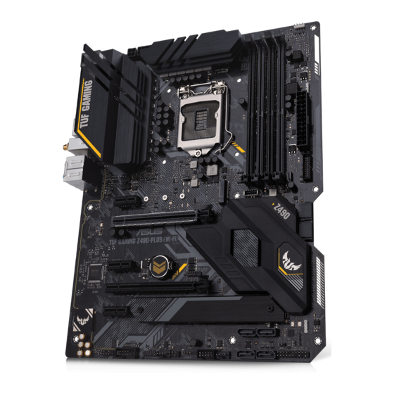
Page 14: Motherboard Layout
Motherboard layout 24.4cm(9.6in) RGB_HEADER1 CPU_FAN CPU_OPT KBMS _U32G1 EATX12V_2 EATX12V_1 DIGI+ 1442K HDMI BOOT U32G2_C2 DRAM U32G2_1 LGA1200 LAN_U32G1_78 CNVI(WIFI) AIO_PUMP AUDIO CHA_FAN1 PCIEX1_1 2280 2260 2242 USB3.2_5 PCIE SATA IRST M.2_2(SOCKET3) PCIEX16_1 ® Intel ® I219-V Intel ® Z490 128Mb BIOS PCIEX1_2... - Page 15 Layout contents Page 1. CPU socket 2. DIMM slots 3. Expansion slots 4. Fan and Pump headers 5. Power connectors 1-10 6. M.2 slots (SOCKET 3) 1-11 7. SATA 6Gb/s ports 1-12 8. USB 3.2 Gen 2 Front Panel connector 1-13 9.
- Page 16 Contact your retailer immediately if the PnP cap is missing, or if you see any damage to the PnP cap/socket contacts/motherboard components. ASUS will shoulder the cost of repair only if the damage is shipment/ transit-related.
- Page 17 DIMM slots The motherboard comes with Dual Inline Memory Modules (DIMM) slots designed for DDR4 (Double Data Rate 4) memory modules. A DDR4 memory module is notched differently from a DDR, DDR2, or DDR3 module. DO NOT install a DDR, DDR2, or DDR3 memory module to the DDR4 slot. Recommended memory configurations TUF GAMING Z490-PLUS (WI-FI)
- Page 18 (D/C) from the same vendor. Check with the vendor to get the correct memory modules. • Visit the ASUS website for the latest QVL. Chapter 1: Product Introduction...
- Page 19 Expansion slots Unplug the power cord before adding or removing expansion cards. Failure to do so may cause you physical injury and damage motherboard components. PCIEX1_1 PCIEX16_1 ® PCIEX1_2 PCIEX16_2 PCIEX1_3 Recommended VGA configuration Slot Description Single VGA Dual VGA PCIe 3.0 x16_1 PCIe 3.0 x16_2 •...
- Page 20 Hyper M.2 X16 series card configuration Slot Description up to 3 Intel SSD on CPU support ® PCIe 3.0 x16_1 x8+x4+x4 • The Hyper M.2 X16 series card is sold separately. • Ensure to install the Hyper M.2 X16 series card to PCIe 3.0 x16_1. If you wish to connect a display, we suggest using the internal VGA or installing a VGA card to PCIe 3.0 x16_2, which will run at x4.
- Page 21 Fan and Pump headers The Fan and Pump headers allow you to connect fans or pumps to cool the system. CPU_FAN CPU_OPT AIO_PUMP CHA_FAN1 CHA_FAN2 CHA_FAN3 • DO NOT forget to connect the fan cables to the fan headers. Insufficient air flow inside the system may damage the motherboard components.
- Page 22 Power connectors These Power connectors allow you to connect your motherboard to a power supply. The power supply plugs are designed to fit in only one orientation. Find the proper orientation and push down firmly until the power supply plugs are fully inserted. EATX12V_2 EATX12V_1 PIN 1...
- Page 23 M.2 slot The M.2 slot allows you to install M.2 devices such as M.2 SSD modules. M.2_2(SOCKET3) M.2_1(SOCKET3) • M.2_1 slot (Key M), type 2242/2260/2280/22110 (supports SATA & PCIe 3.0 x4 mode). • M.2_2 slot (Key M), type 2242/2260/2280 (supports SATA & PCIe 3.0 x4 mode). •...
- Page 24 When a device is installed on the M.2_2 socket, SATA6G_56 ports cannot be used. • Before creating a RAID set, refer to the RAID Configuration Guide. You can download the RAID Configuration Guide from the ASUS website. Chapter 1: Product Introduction 1-12...
- Page 25 USB 3.2 Gen 2 Front Panel connector The USB 3.2 Gen 2 connector allows you to connect a USB 3.2 Gen 2 module for additional USB 3.2 Gen 2 ports. The USB 3.2 Gen 2 connector provides data transfer speeds of up to 10 Gb/s. USB3.2_5 The USB 3.2 Gen 2 module is purchased separately.
- Page 26 USB 3.2 Gen 1 header The USB 3.2 Gen 1 header allows you to connect a USB 3.2 Gen 1 module for additional USB 3.2 Gen 1 ports. The USB 3.2 Gen 1 header provides data transfer speeds of up to 5 Gb/s. U32G1_910 PIN 1 USB3+5V...
- Page 27 USB 2.0 header Connect the USB module cable to these connectors, then install the module to a slot opening at the front of the system chassis. These USB headers comply with USB 2.0 specifications and support up to 480 Mbps connection speed. USB6 PIN 1 USB1112...
- Page 28 Aura Addressable Gen2 header The Addressable Gen2 header allows you to connect individually addressable RGB WS2812B LED strips or WS2812B based LED strips. ADD_GEN2 Ground Data PIN 1 The Addressable Gen2 header supports WS2812B addressable RGB LED strips (5V/ Data/Ground), with a maximum power rating of 3A (5V), and the addressable headers on this board can handle a combined maximum of 500 LEDs.
- Page 29 AURA RGB LED header The AURA RGB LED header allows you to connect RGB LED strips. RGB_HEADER1 PIN 1 +12V G R B RGB_HEADER2 +12V PIN 1 The AURA RGB LED header supports 5050 RGB multi-color LED strips (12V/G/R/B), with a maximum power rating of 3A (12V).
- Page 30 Clear CMOS header This header allows you to clear the Real Time Clock (RTC) RAM in CMOS. You can clear the CMOS memory of date, time, and system setup parameters by erasing the CMOS RTC RAM data. The onboard button cell battery powers the RAM data in CMOS, which include system setup information such as system passwords.
- Page 31 COM Port header This connector is for a serial (COM) port. Connect the serial port module cable to this connector, then install the module to a slot opening at the back of the system chassis. PIN 1 The COM module is purchased separately. Front Panel Audio header The front panel audio header is for a chassis-mounted front panel audio I/O module that supports HD Audio.
- Page 32 System Panel header The System Panel header supports several chassis-mounted functions. PLED PWRSW SPEAKER CHASSIS PANEL PIN 1 HDD_LED RESET PLED • System Power LED header (PLED) The 2-pin header allows you to connect the System Power LED. The System Power LED lights up when the system is connected to a power source, or when you turn on the system power, and blinks when the system is in sleep mode.
- Page 33 Thunderbolt header The Thunderbolt header allows you to connect an add-on Thunderbolt I/O card that supports Intel’s Thunderbolt Technology, allowing you to connect up to six Thunderbolt-enabled devices and a DisplayPort-enabled display in a daisy-chain configuration. TB_HEADER PIN 1 The add-on Thunderbolt I/O card and Thunderbolt cables are purchased separately. Q-LEDs The Q-LEDs check key components (CPU, DRAM, VGA, and booting devices) during the motherboard booting process.
- Page 34 Chapter 1: Product Introduction 1-22...
-
Page 35: Building Your Pc System
NOT install a CPU designed for LGA1155, LGA1156, and LGA1151 sockets on the LGA1200 socket. • ASUS will not cover damages resulting from incorrect CPU installation/removal, incorrect CPU orientation/placement, or other damages resulting from negligence by the user. TUF GAMING Z490-PLUS (WI-FI) - Page 36 Chapter 2: Basic Installation...
-
Page 37: Cooling System Installation
2.1.2 Cooling system installation Apply Thermal Interface Material to the CPU cooling system and CPU before you install the cooling system, if necessary. To install a CPU heatsink and fan assembly TUF GAMING Z490-PLUS (WI-FI) - Page 38 To install an AIO cooler If you wish to install an AIO cooler, we recommend installing the AIO cooler after installing the motherboard into the chassis. AIO_PUMP CPU_FAN CPU_OPT Chapter 2: Basic Installation...
-
Page 39: Dimm Installation
2.1.3 DIMM installation To remove a DIMM TUF GAMING Z490-PLUS (WI-FI) -
Page 40: M.2 Installation
2.1.4 M.2 installation For type 22110 M.2 on M.2_1 slot For type 2242 / 2260 / 2280 M.2 on M.2_1 slot OPTIONAL OPTIONAL • This M.2 rubber pad is optional for when installing a single sided M.2 storage device. Ensure to install the bundled M.2 rubber pad before installing your single sided M.2 storage device. -
Page 41: Fan Bracket Installation
2.1.5 Fan bracket installation ® When using high performance settings whilst overclocking, ensure to install the fan holder for additional fan(s). • You may install 12V (1A, 12W), 40mm x 40mm fans or 50mm x 50mm fans. • Ensure to use the bundled screws that came with your fans. •... -
Page 42: Motherboard Installation
2.1.6 Motherboard installation Install the ASUS I/O Shield to the chassis rear I/O panel. Some sharp edges and points might cause physical injury. We recommend you put on cut or puncture resistant gloves before motherboard and I/O shield installation. Place the motherboard into the chassis, ensuring that its rear I/O ports are aligned to the chassis’... - Page 43 Place nine (9) screws into the holes indicated by circles to secure the motherboard to the chassis. ® DO NOT over tighten the screws! Doing so can damage the motherboard. TUF GAMING Z490-PLUS (WI-FI)
-
Page 44: Atx Power Connection
2.1.7 ATX power connection • DO NOT connect the 4-pin power plug only, the motherboard may overheat under heavy usage. • Ensure to connect the 8-pin power plug, or connect both the 8-pin and 4-pin power plugs. Chapter 2: Basic Installation 2-10... -
Page 45: Sata Device Connection
2.1.8 SATA device connection TUF GAMING Z490-PLUS (WI-FI) 2-11... -
Page 46: Front I/O Connector
2.1.9 Front I/O connector To install the front panel header To install USB 3.2 Gen 2 connector USB 3.2 Gen 2 This connector will only fit in one orientation. Push the connector until it clicks into place. To install USB 3.2 Gen 1 connector To install USB 2.0 connector USB 3.1 Gen 1 USB 2.0... -
Page 47: Expansion Card Installation
2.1.10 Expansion card installation To install PCIe x16 cards To install PCIe x1 cards TUF GAMING Z490-PLUS (WI-FI) 2-13... - Page 48 To install ThunderboltEX 3-TR card 6-pin PCIe power connector USB Type-C ® port connects to Thunderbolt devices MiniDP in port connects to DP out port on the motherboard or a VGA card USB 2.0 header Thunderbolt header Ensure to install the ThunderboltEX 3-TR card to a PCIe slot from PCH. •...
-
Page 49: Wi-Fi Antenna Installation
2.1.11 Wi-Fi antenna installation Installing the ASUS 2x2 dual band W-Fi antenna Connect the bundled ASUS 2x2 dual band Wi-Fi antenna connector to the Wi-Fi ports at the back of the chassis. • Ensure that the ASUS 2x2 dual band Wi-Fi antenna is securely installed to the Wi-Fi ports. -
Page 50: Motherboard Rear And Audio Connections
Motherboard rear and audio connections 2.2.1 Rear I/O connection Rear panel connectors PS/2 mouse/keyboard combo port DisplayPort USB 3.2 Gen 2 Type-A port Ethernet (RJ-45) port* USB 3.2 Gen 1 Type-A ports 34 and 78 HDMI™ port USB Type-C ® Wi-Fi 802.11 a/b/g/n/ac/ax, Bluetooth V5.1 Optical S/PDIF OUT port audio jacks**... -
Page 51: Audio I/O Connections
* Ethernet port LED indications Activity Link LED Speed LED ACT/LINK SPEED Status Description Status Description No link 10 Mbps connection Orange Linked Orange 100 Mbps connection Blinking LAN port Data activity Green 1 Gbps connection ** Audio 2, 4, 5.1 or 7.1-channel configuration Headset Port 4-channel... - Page 52 Connect to Stereo Speakers Connect to 2-channel Speakers Connect to 4-channel Speakers Chapter 2: Basic Installation 2-18...
- Page 53 Connect to 5.1-channel Speakers Connect to 7.1-channel Speakers TUF GAMING Z490-PLUS (WI-FI) 2-19...
-
Page 54: Starting Up For The First Time
Starting up for the first time After making all the connections, replace the system case cover. Ensure that all switches are off. Connect the power cord to the power connector at the back of the system chassis. Connect the power cord to a power outlet that is equipped with a surge protector. Turn on the devices in the following order: Monitor External SCSI devices (starting with the last device on the chain) -
Page 55: Chapter 3: Bios And Raid Support
Knowing BIOS The new ASUS UEFI BIOS is a Unified Extensible Interface that complies with UEFI architecture, offering a user-friendly interface that goes beyond the traditional keyboard- only BIOS controls to enable a more flexible and convenient mouse input. You can easily navigate the new UEFI BIOS with the same smoothness as your operating system. -
Page 56: Bios Setup Program
BIOS setup program Use the BIOS Setup to update the BIOS or configure its parameters. The BIOS screen include navigation keys and brief onscreen help to guide you in using the BIOS Setup program. Entering BIOS at startup To enter BIOS Setup at startup, press <Delete> or <F2> during the Power-On Self Test (POST). -
Page 57: Asus Ez Flash 3
ASUS EZ Flash 3 The ASUS EZ Flash 3 feature allows you to update the BIOS without using an OS-based utility. Ensure to load the BIOS default settings to ensure system compatibility and stability. Select the Load Optimized Defaults item under the Exit menu or press hotkey <F5>. -
Page 58: Asus Crashfree Bios 3
The BIOS file in the motherboard support DVD may be older than the BIOS file published on the ASUS official website. If you want to use the newer BIOS file, download the file at https://www.asus.com/support/ and save it to a USB flash drive. -
Page 59: Raid Configurations
For more information on configuring your RAID sets, please refer to the RAID Configuration Guide which you can find at https://www.asus.com/support, or by scanning the QR code. RAID definitions RAID 0 (Data striping) optimizes two identical hard disk drives to read and write data in parallel, interleaved stacks. - Page 60 Chapter 3: BIOS Setup...
-
Page 61: Appendix
Appendix Appendix Notices FCC Compliance Information Responsible Party: Asus Computer International Address: 48720 Kato Rd., Fremont, CA 94538, USA Phone / Fax No: (510)739-3777 / (510)608-4555 Identification of the assembled product: INTEL Wi-Fi 6 AX201 Identification of the modular components used in the assembly:... - Page 62 Compliance Statement of Innovation, Science and Economic Development Canada (ISED) This device complies with Innovation, Science and Economic Development Canada licence exempt RSS standard(s). Operation is subject to the following two conditions: (1) this device may not cause interference, and (2) this device must accept any interference, including interference that may cause undesired operation of the device.
- Page 63 Google™ License Terms Copyright© 2020 Google Inc. All Rights Reserved. Licensed under the Apache License, Version 2.0 (the “License”); you may not use this file except in compliance with the License. You may obtain a copy of the License at: http://www.apache.org/licenses/LICENSE-2.0 Unless required by applicable law or agreed to in writing, software distributed under the License is distributed on an “AS IS”...
- Page 64 ASUS products sold in Vietnam, on or after September 23, 2011,meet the requirements of the Vietnam Circular 30/2011/TT-BCT. Các sản phẩm ASUS bán tại Việt Nam, vào ngày 23 tháng 9 năm2011 trở về sau, đều phải đáp ứng các yêu cầu của Thông tư 30/2011/TT-BCT của Việt Nam.
- Page 65 DO NOT throw the motherboard in municipal waste. This product has been designed to enable proper reuse of parts and recycling. This symbol of the crossed out wheeled bin indicates that the product (electrical and electronic equipment) should not be placed in municipal waste.
- Page 66 2014/53/EU. Cijeli di: https://www.asus.com/support/ tekst EU izjave o sukladnosti dostupan je na https://www.asus.com/support/ WiFi yang Beroperasi pada 5150-5350 MHz akan terbatas untuk penggunaan WiFi koji radi na opsegu frekvencija 5150-5350 MHz bit će ograničen na...
- Page 67 ASUSTek Computer Inc. tukaj izjavlja, da je ta naprava skladna s temeljnimi CCAH18LP3520T2 Intel® Wi-Fi 6 AX201 zahtevami in drugimi relevantnimii določili Direktive 2014/53/EU. Polno Model: AX201NGW besedilo izjave EU o skladnosti je na voljo na https://www.asus.com/ IFETEL: RCPINAX18-2041 support/ FCC ID: PD9AX201NG CMIT ID: 2018AJ7550(M) R-C-INT-AX201NGW WiFi, ki deluje v pasovnem območju 5150–5350 MHz, mora biti v državah,...
-
Page 68: Asus Contact Information
+1-510-739-3777 +1-510-608-4555 Web site https://www.asus.com/us/ Technical Support Support fax +1-812-284-0883 Telephone +1-812-282-2787 Online support https://qr.asus.com/techserv ASUS COMPUTER GmbH (Germany and Austria) Address Harkortstrasse 21-23, 40880 Ratingen, Germany Web site https://www.asus.com/de Online contact https://www.asus.com/support/Product/ContactUs/ Services/questionform/?lang=de-de Technical Support Telephone (DE) +49-2102-5789557 Telephone (AT)
Need help?
Do you have a question about the TUF GAMING Z490-PLUS WI-FI and is the answer not in the manual?
Questions and answers