Table of Contents
Advertisement
Advertisement
Table of Contents

Related Manuals for Asus PRIME Z490-V


Summary of Contents for Asus PRIME Z490-V
- Page 1 PRIME Z490-V...
- Page 2 Product warranty or service will not be extended if: (1) the product is repaired, modified or altered, unless such repair, modification of alteration is authorized in writing by ASUS; or (2) the serial number of the product is defaced or missing.
-
Page 3: Table Of Contents
Contents Safety information ...................... iv About this guide ......................v PRIME Z490-V specifications summary ..............vi Connectors with shared bandwidth ................x Package contents ....................... xi Installation tools and components ................xii Chapter 1: Product Introduction Before you proceed ................... 1-1 Motherboard layout.................. -
Page 4: Safety Information
Safety information Electrical safety • To prevent electrical shock hazard, disconnect the power cable from the electrical outlet before relocating the system. • When adding or removing devices to or from the system, ensure that the power cables for the devices are unplugged before the signal cables are connected. If possible, disconnect all power cables from the existing system before you add a device. • Before connecting or removing signal cables from the motherboard, ensure that all power cables are unplugged. -
Page 5: About This Guide
Refer to the following sources for additional information and for product and software updates. ASUS website The ASUS website (www.asus.com) provides updated information on ASUS hardware and software products. Optional documentation Your product package may include optional documentation, such as warranty flyers, that may have been added by your dealer. -
Page 6: Prime Z490-V Specifications Summary
OptiMem * 10 Gen Intel Core™ i9/i7 CPUs support 2933/2800/2666/2400/2133 natively. ® * Refer to www.asus.com for the Memory QVL (Qualified Vendors Lists). 1 x DisplayPort 1.4** 1 x HDMI 1.4b Graphics * Graphics specifications may vary between CPU types. - Page 7 PRIME Z490-V specifications summary Rear USB (Total 6 ports) 2 x USB 3.2 Gen 2 ports (2 x Type-A) 2 x USB 3.2 Gen 1 ports (2 x Type-A) 2 x USB 2.0 ports (2 x Type-A) Front USB (Total 8 ports) 2 x USB 3.2 Gen 1 headers support additional 4 USB 3.2 Gen 1 ports...
- Page 8 But the ADD_Gen2 header and the two RGB headers will affect transfer rate only when you adjust their lighting effect. ASUS 5X PROTECTION III - ASUS DIGI+ VRM (- Digital power design with Dr. MOS) - ASUS LANGuard - ASUS Overvoltage Protection...
- Page 9 Windows 10 - 64 bit Operating System ® ATX Form Factor Form Factor 12 inch x 9.6 inch (30.5 cm x 24.4 cm) Specifications are subject to change without notice. Please refer to the ASUS website for the latest specifications.
-
Page 10: Connectors With Shared Bandwidth
Connectors with shared bandwidth KBMS_USB910 CPU_FAN EATX12V_2 EATX12V_1 DIGI+ HDMI 1442K U32G2_12 LGA1200 LAN_U32G1_56 AIO_PUMP AUDIO CHA_FAN1 PCIEX1_1 2280 2260 2242 PCIE SATA IRST M.2_1(SOCKET3) Realtek ® PCIEX16_1 8111H Intel ® Z490 128Mb BIOS PCIEX1_2 Super BATTERY PCIEX16_2 PCIE SATA IRST PCIEX1_3 M.2_2(SOCKET3) -
Page 11: Package Contents
Package contents Check your motherboard package for the following items. Motherboard 1 x PRIME Z490-V motherboard Cables 2 x SATA 6Gb/s cables 1 x I/O Shield Miscellaneous 1 x M.2 SSD screw package 1 x M.2 Key E screw package... -
Page 12: Installation Tools And Components
Installation tools and components Phillips (cross) screwdriver PC chassis Power supply unit Intel LGA 1200 CPU Intel LGA 1200 compatible CPU Fan ® ® DDR4 DIMM SATA hard disk drive SATA optical disc drive (optional) Graphics card (optional) M.2 SSD module (optional) 1 Bag of screws The tools and components in the table above are not included in the motherboard package. -
Page 13: Chapter 1: Product Introduction
Chapter 1: Product Introduction Product Introduction Before you proceed Take note of the following precautions before you install motherboard components or change any motherboard settings. • Unplug the power cord from the wall socket before touching any component. • Before handling components, use a grounded wrist strap or touch a safely grounded object or a metal object, such as the power supply case, to avoid damaging them due to static electricity. • Hold components by the edges to avoid touching the ICs on them. • Whenever you uninstall any component, place it on a grounded antistatic pad or in the bag that came with the component. • Before you install or remove any component, ensure that the ATX power supply is switched off or the power cord is detached from the power supply. Failure to do so may cause severe damage to the motherboard, peripherals, or components. PRIME Z490-V... -
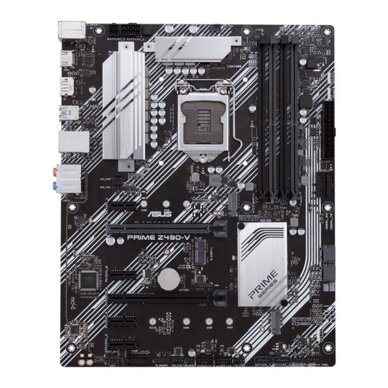
Page 14: Motherboard Layout
Motherboard layout 24.4cm(9.6in) KBMS_USB910 CPU_FAN EATX12V_2 EATX12V_1 DIGI+ HDMI 1442K U32G2_12 LGA1200 LAN_U32G1_56 AIO_PUMP AUDIO CHA_FAN1 PCIEX1_1 2280 2260 2242 PCIE SATA IRST M.2_1(SOCKET3) Realtek ® PCIEX16_1 8111H Intel ® Z490 128Mb BIOS PCIEX1_2 Super BATTERY PCIEX16_2 PCIE SATA IRST PCIEX1_3 M.2_2(SOCKET3) 22110... - Page 15 7. SATA 6Gb/s ports 1-12 8. USB 3.2 Gen 1 headers 1-13 9. USB 2.0 headers 1-14 10. AURA Addressable Gen 2 header 1-15 11. AURA RGB headers 1-16 12. Clear CMOS header 1-17 13. COM Port header 1-18 14. Front Panel Audio header 1-18 15. M.2 slot (Key E) 1-19 16. S/PDIF Out header 1-21 17. System Panel header 1-20 18. Thunderbolt header 1-21 19. SPI TPM header (14-1pin) 1-19 PRIME Z490-V...
- Page 16 CPU socket The motherboard comes with a LGA1200 socket designed for 10 Gen Intel Core ® Pentium Gold and Celeron Processors. ® ® LGA1200 • Ensure that you install the correct CPU designed for LGA1200 socket only. DO NOT install a CPU designed for other sockets on the LGA1200 socket. • The CPU fits in only one correct orientation. DO NOT force the CPU into the socket to prevent bending the connectors on the socket and damaging the CPU. • Ensure that all power cables are unplugged before installing the CPU. • Upon purchase of the motherboard, ensure that the PnP cap is on the socket and the socket contacts are not bent. Contact your retailer immediately if the PnP cap is missing, or if you see any damage to the PnP cap/socket contacts/motherboard components. ASUS will shoulder the cost of repair only if the damage is shipment/ transit-related. • Keep the cap after installing the motherboard. ASUS will process Return Merchandise Authorization (RMA) requests only if the motherboard comes with the cap on the LGA1200 socket. • The product warranty does not cover damage to the socket contacts resulting from incorrect CPU installation/removal, or misplacement/loss/incorrect removal of the PnP cap. Chapter 1: Product Introduction...
- Page 17 DIMM slots This motherboard comes with four Double Data Rate 4 (DDR4) Dual Inline Memory Module (DIMM) sockets. A DDR4 memory module is notched differently from a DDR, DDR2, or DDR3 module. DO NOT install a DDR, DDR2, or DDR3 memory module to the DDR4 slot. Recommended memory configurations PRIME Z490-V...
- Page 18 Memory configurations You may install 2 GB, 4 GB, 8 GB, 16 GB, and 32 GB unbuffered and non-ECC DDR4 DIMMs into the DIMM sockets. You may install varying memory sizes in Channel A and Channel B. The system maps the total size of the lower-sized channel for the dual-channel configuration. Any excess memory from the higher-sized channel is then mapped for single-channel operation. • The default memory operation frequency is dependent on its Serial Presence Detect (SPD), which is the standard way of accessing information from a memory module. Under the default state, some memory modules for overclocking may operate at a lower frequency than the vendor-marked value. • For system stability, use a more efficient memory cooling system to support a full memory load or overclocking condition. • Always install the DIMMS with the same CAS Latency. For an optimum compatibility, we recommend that you install memory modules of the same version or data code (D/C) from the same vendor. Check with the vendor to get the correct memory modules. • Visit the ASUS website for the latest QVL. Chapter 1: Product Introduction...
- Page 19 Expansion slots Unplug the power cord before adding or removing expansion cards. Failure to do so may cause you physical injury and damage motherboard components. PCIEX1_1 PCIEX16_1 PCIEX1_2 PCIEX16_2 PCIEX1_3 PCIEX1_4 Recommended VGA configuration Slot Description Single VGA Dual VGA PCIe x16_1 PCIe x16_2 • We recommend that you provide sufficient power when running CrossFireX™ mode. • Ensure to connect the 8-pin and 4-pin power plugs when running CrossFireX™ mode. • Connect a chassis fan to the chassis fan connectors when using multiple graphics cards for better thermal environment. PRIME Z490-V...
- Page 20 Hyper M.2 X16 series card configuration Slot Description up to 3 Intel SSD on CPU support ® PCIe x16_1 x8+x4+x4 • Hyper M.2 X16 series card is sold separately. • Ensure to install the Hyper M.2 X16 series card to PCIe x16_1. If you wish to connect a display, we suggest using the internal VGA or installing a VGA card to PCIe x16_2, which will run at x4. • Enable the Hyper M.2 X16 series card under BIOS settings. Chapter 1: Product Introduction...
- Page 21 Fan and Pump headers The Fan and Pump headers allow you to connect fans or pumps to cool the system. CPU_FAN AIO_PUMP CHA_FAN1 CHA_FAN2 CHA_FAN3 • DO NOT forget to connect the fan cables to the fan headers. Insufficient air flow inside the system may damage the motherboard components. These are not jumpers! Do not place jumper caps on the fan headers! • Ensure the cable is fully inserted into the header. Header Max. Current Max. Power Default Speed Shared Control CPU_FAN Q-Fan Controlled CHA_FAN1 Q-Fan Controlled CHA_FAN2 Q-Fan Controlled CHA_FAN3 Q-Fan Controlled AIO_PUMP Full-Speed PRIME Z490-V...
- Page 22 Power connectors These Power connectors allow you to connect your motherboard to a power supply. The power supply plugs are designed to fit in only one orientation. Find the proper orientation and push down firmly until the power supply plugs are fully inserted. EATX12V_1 EATX12V_2 PIN 1 PIN 1 EATXPWR +3 Volts +12 Volts +5 Volts +12 Volts +5 Volts +5V Standby +5 Volts Power OK -5 Volts +5 Volts +5 Volts PSON# +3 Volts -12 Volts +3 Volts +3 Volts PIN 1 •...
- Page 23 M.2 slots The M.2 slots allow you to install M.2 devices such as M.2 SSD modules. M.2_1(SOCKET3) M.2_2(SOCKET3) • M.2_1 slot (Key M), type 2242/2260/2280 (supports SATA & PCIe 3.0 x4 modes). • M.2_2 slot (Key M), type 2242/2260/2280/22110 (supports SATA & PCIe 3.0 x4 modes). • When a device in SATA mode is installed on the M.2_1 socket, SATA6G_2 port cannot be used. • M.2 slots support IRST (Intel Rapid Storage Technology). ® The M.2 SSD module is purchased separately. PRIME Z490-V 1-11...
- Page 24 SATA 6Gb/s ports The SATA 6Gb/s ports allow you to connect SATA devices such as optical disc drives and hard disk drives via a SATA cable. RSATA_TXP RSATA_TXN SATA6G_1 RSATA_RXN RSATA_RXP SATA6G_2 SATA6G_3 SATA6G_4 If you installed SATA storage devices, you can create a RAID 0, 1, 5, and 10 configuration with the Intel Rapid Storage Technology through the onboard Intel Z490 chipset. ® ® The slots are set to [AHCI Mode] by default. If you intend to create a SATA RAID set • using these connectors, set the SATA Mode item in the BIOS to [Intel RST Premium (RAID)]. • When a device in SATA mode is installed on the M.2_1 socket, SATA6G_2 port cannot be used. • Before creating a RAID set, refer to the RAID Configuration Guide. You can download the RAID Configuration Guide from the ASUS website. Chapter 1: Product Introduction 1-12...
- Page 25 USB 3.2 Gen 1 headers The USB 3.2 Gen 1 headers allow you to connect a USB 3.2 Gen 1 module for additional USB 3.2 Gen 1 ports. The USB 3.2 Gen 1 headers provide data transfer speeds of up to 5 Gb/s. U32G1_34 U32G1_78 PIN 1 USB3+5V USB3+5V IntA_P1_SSRX- IntA_P2_SSRX- IntA_P1_SSRX+ IntA_P2_SSRX+ IntA_P1_SSTX- IntA_P2_SSTX- IntA_P1_SSTX+ IntA_P2_SSTX+ IntA_P1_D- IntA_P2_D- IntA_P1_D+ IntA_P2_D+ The USB 3.2 Gen 1 module is purchased separately. The plugged USB 3.2 Gen 1 device may run on xHCI or EHCI mode depending on the operating system’s setting. PRIME Z490-V 1-13...
- Page 26 USB 2.0 headers The USB 2.0 headers allow you to connect a USB module for additional USB 2.0 ports. The USB 2.0 headers provide data transfer speeds of up to 480 Mb/s. USB_E12 USB1112 PIN 1 DO NOT connect a 1394 cable to the USB connectors. Doing so will damage the motherboard! The USB 2.0 module is purchased separately. Chapter 1: Product Introduction 1-14...
- Page 27 AURA Addressable Gen 2 header The Addressable Gen 2 header allows you to connect individually addressable RGB WS2812B LED strips or WS2812B based LED strips. ADD_GEN2 Ground Data PIN 1 The Addressable Gen 2 header supports WS2812B addressable RGB LED strips (5V/ Data/Ground), with a maximum power rating of 3A (5V) and the addressable header on this board can handle a combined maximum of 500 LEDs. Before you install or remove any component, ensure that the power supply is switched off or the power cord is detached from the power supply. Failure to do so may cause severe damage to the motherboard, peripherals, or components. • Actual lighting and color will vary with LED strip. • If your LED strip does not light up, check if the addressable RGB LED strip is connected in the correct orientation, and the 5V connector is aligned with the 5V header on the motherboard. • The addressable RGB LED strip will only light up when the system is powered on. • The addressable RGB LED strip is purchased separately. PRIME Z490-V 1-15...
- Page 28 AURA RGB headers The RGB headers allow you to connect RGB LED strips. RGB_HEADER1 RGB_HEADER2 +12V PIN 1 The RGB headers support 5050 RGB multi-color LED strips (12V/G/R/B), with a maximum power rating of 3A (12V). Before you install or remove any component, ensure that the power supply is switched off or the power cord is detached from the power supply. Failure to do so may cause severe damage to the motherboard, peripherals, or components. • Actual lighting and color will vary with LED strip. • If your LED strip does not light up, check if the RGB LED extension cable and the RGB LED strip is connected in the correct orientation, and the 12V connector is aligned with the 12V header on the motherboard. • The LED strip will only light up when the system is powered on. • The LED strip is purchased separately. Chapter 1: Product Introduction 1-16...
- Page 29 Clear CMOS header This header allows you to clear the Real Time Clock (RTC) RAM in CMOS. You can clear the CMOS memory of date, time, and system setup parameters by erasing the CMOS RTC RAM data. The onboard button cell battery powers the RAM data in CMOS, which include system setup information such as system passwords. CLRTC PIN 1 To erase the RTC RAM: Turn OFF the computer and unplug the power cord. Use a metal object such as a screwdriver to short the two pins. Plug the power cord and turn on the computer. Hold down the <Del> key during the boot process and enter BIOS setup to re- enter data. If the steps above do not help, remove the onboard battery and short the two pins again to clear the CMOS RTC RAM data. After clearing the CMOS, reinstall the battery. PRIME Z490-V 1-17...
- Page 30 COM Port header This connector is for a serial (COM) port. Connect the serial port module cable to this connector, then install the module to a slot opening at the back of the system chassis. PIN 1 The COM module is purchased separately. Front Panel Audio header The front panel audio header is for a chassis-mounted front panel audio I/O module that supports HD Audio. Connect one end of the front panel audio I/O module cable to this header. We recommend that you connect a high-definition front panel audio module to this connector to avail of the motherboard’s high-definition audio capability. Chapter 1: Product Introduction 1-18...
- Page 31 This socket allows you to install an M.2 (WIFI) module. M.2(WIFI) PIN2 PIN 1 S_USB_PP10_R S_USB_PN10_R X_WIFI_TXP X_WIFI_TXN CL_RST# CL_DATA X_WIFI_RXP CL_CLK X_WIFI_RXN C_PCIE_WIFI C_PCIE_WIFI# S_SUSCLK S_PLTRST# L1_WIFI_CLKREQ# BT_ISOLATE#_R S_WAKE# M2_ISOLATE#_R PIN74 PIN 75 The M.2 (NGFF) SSD module is sold separately. SPI TPM header (14-1pin) This header supports a Trusted Platform Module (TPM) system with a Serial Peripheral Interface (SPI), allowing you to securely store keys, digital certificates, passwords, and data. A TPM system also helps enhance network security, protects digital identities, and ensures platform integrity. PIN 1 The TPM module is purchased separately. PRIME Z490-V 1-19...
- Page 32 System Panel header The System Panel header supports several chassis-mounted functions. PLED PWRSW SPEAKER PANEL PIN 1 HDD_LED RESET PLED • System power LED (2-pin PLED) This 2-pin header is for the system power LED. Connect the chassis power LED cable to this header. The system power LED lights up when you turn on the system power, and blinks when the system is in sleep mode. • Hard disk drive activity LED (2-pin HDD_LED) This 2-pin header is for the HDD Activity LED. Connect the HDD Activity LED cable to this header. The HDD LED lights up or flashes when data is read from or written to the HDD. • System warning speaker (4-pin SPEAKER) This 4-pin header is for the chassis-mounted system warning speaker. The speaker allows you to hear system beeps and warnings. • ATX power button/soft-off button (2-pin PWRSW) This header is for the system power button. Pressing the power button turns the system on or puts the system in sleep or soft-off mode depending on the operating system settings. Pressing the power switch for more than four seconds while the system is ON turns the system OFF. • Reset button (2-pin RESET) This 2-pin header is for the chassis-mounted reset button for system reboot without turning off the system power. Chapter 1: Product Introduction 1-20...
- Page 33 Thunderbolt header The Thunderbolt header allows you to connect an add-on Thunderbolt I/O card that supports Intel’s Thunderbolt Technology, allowing you to connect up to six Thunderbolt-enabled devices and a DisplayPort-enabled display in a daisy-chain configuration. TB_HEADER PIN 1 The add-on Thunderbolt I/O card and Thunderbolt cables are purchased separately. S/PDIF Out header This header is for an additional Sony/Philips Digital Interface (S/PDIF) port. Connect the S/PDIF Out module cable to this header, then install the module to a slot opening at the back of the system chassis. SPDIF_OUT The S/PDIF Out module is purchased separately. PRIME Z490-V 1-21...
- Page 34 Chapter 1: Product Introduction 1-22...
-
Page 35: Chapter 2: Basic Installation
The diagrams in this section are for reference only. The motherboard layout may vary with models, but the installation steps are the same for all models. 2.1.1 CPU installation • Ensure that you install the correct CPU designed for LGA1200 socket only. DO NOT install a CPU designed for LGA1155, LGA1156, and LGA1151 sockets on the LGA1200 socket. • ASUS will not cover damages resulting from incorrect CPU installation/removal, incorrect CPU orientation/placement, or other damages resulting from negligence by the user. PRIME Z490-V... - Page 36 Chapter 2: Basic Installation...
-
Page 37: Cooling System Installation
2.1.2 Cooling system installation Apply Thermal Interface Material to the CPU cooling system and CPU before you install the cooling system, if necessary. To install a CPU heatsink and fan assembly PRIME Z490-V... - Page 38 To install an AIO cooler If you wish to install an AIO cooler, we recommend installing the AIO cooler after installing the motherboard into the chassis. AIO_PUMP CPU_FAN Chapter 2: Basic Installation...
-
Page 39: Dimm Installation
2.1.3 DIMM installation To remove a DIMM PRIME Z490-V... -
Page 40: Installation
2.1.4 M.2 installation The M.2 is purchased separately. Chapter 2: Basic Installation... -
Page 41: Motherboard Installation
2.1.5 Motherboard installation Install the ASUS I/O Shield to the chassis rear I/O panel. Some sharp edges and points might cause physical injury. We recommend you put on cut or puncture resistant gloves before motherboard and I/O shield installation. Place the motherboard into the chassis, ensuring that its rear I/O ports are aligned to the chassis’ rear I/O panel. PRIME Z490-V... - Page 42 Place nine (9) screws into the holes indicated by circles to secure the motherboard to the chassis. DO NOT over tighten the screws! Doing so can damage the motherboard. Chapter 2: Basic Installation...
-
Page 43: Atx Power Connection
2.1.6 ATX power connection • DO NOT connect the 4-pin power plug only. The motherboard may overheat under heavy usage. • Ensure to connect the 8-pin power plug, or connect both the 8-pin and 4-pin power plugs. PRIME Z490-V... -
Page 44: Sata Device Connection
2.1.7 SATA device connection Chapter 2: Basic Installation 2-10... -
Page 45: Front I/O Connector
2.1.8 Front I/O connector To install the front panel connector To install USB 3.2 Gen 1 connector USB 3.2 Gen 1 To install USB 2.0 connector To install front panel audio connector AAFP USB 2.0 PRIME Z490-V 2-11... -
Page 46: Expansion Card Installation
2.1.9 Expansion card installation To install PCIe x16 cards To install PCIe x1 cards Chapter 2: Basic Installation 2-12... - Page 47 Thunderbolt devices MiniDP in port connects to DP out port on the motherboard or a VGA card USB 2.0 header Thunderbolt header Ensure to install the ThunderboltEX 3-TR card to a PCIe slot from PCH. • Step 6 is optional. Please connect a 6-pin PCIe power connector when you wish to use the USB Type-C port Thunderbolt quick charge feature to charge a 5V or more ® device. The ThunderboltEX 3-TR card can support quick charging up to 100W. • The TypeC_1 port can support up to 20V devices, and the TypeC_2 port can support up to 9V devices when the 6-pin PCIe power connector is connected. • The Thunderbolt card is sold separately. PRIME Z490-V 2-13...
-
Page 48: Motherboard Rear And Audio Connections
Motherboard rear and audio connections 2.2.1 Rear I/O connection Rear panel connectors PS/2 mouse/keyboard combo port Ethernet (RJ-45) port* USB 2.0 ports 9 and 10 HDMI™ port DisplayPort USB 3.2 Gen 2 Type-A ports 1 and 2 USB 3.2 Gen 1 Type-A ports 5 and 6 Audio jacks** * and ** : Refer to the tables on the next page for Ethernet port LEDs, and audio port definitions. •... -
Page 49: Audio I/O Connections
Front Speaker Out Front Speaker Out Front Speaker Out Pink Mic In Mic In Mic In Mic In Orange – – Center/Sub Center/Sub woofer woofer Black – Rear Speaker Out Rear Speaker Out Rear Speaker Out Gray – – – Side Speaker Out 2.2.2 Audio I/O connections Audio I/O ports Connect to Headphone and Mic PRIME Z490-V 2-15... - Page 50 Connect to Stereo Speakers Connect to 2-channel Speakers Connect to 4-channel Speakers Chapter 2: Basic Installation 2-16...
- Page 51 Connect to 5.1-channel Speakers Connect to 7.1-channel Speakers PRIME Z490-V 2-17...
-
Page 52: Starting Up For The First Time
Starting up for the first time After making all the connections, replace the system case cover. Ensure that all switches are off. Connect the power cord to the power connector at the back of the system chassis. Connect the power cord to a power outlet that is equipped with a surge protector. Turn on the devices in the following order: a. Monitor b. External SCSI devices (starting with the last device on the chain) System power After applying power, the system power LED on the system front panel case lights up. For systems with ATX power supplies, the system LED lights up when you press the ATX power button. If your monitor complies with the “green” standards or if it has a “power standby” feature, the monitor LED may light up or change from orange to green after the system LED turns on. The system then runs the power-on self tests (POST). While the tests are running, the BIOS beeps (refer to the BIOS beep codes table) or additional messages appear on the screen. If you do not see anything within 30 seconds from the time you turned on the power, the system may have failed a power-on test. Check the jumper settings and connections or call your retailer for assistance. BIOS Beep Description VGA detected One short beep Quick boot set to disabled No keyboard detected One continuous beep followed by two No memory detected short beeps then a pause (repeated) -
Page 53: Chapter 3: Bios And Raid Support
BIOS and RAID Support Knowing BIOS The new ASUS UEFI BIOS is a Unified Extensible Interface that complies with UEFI architecture, offering a user-friendly interface that goes beyond the traditional keyboard- only BIOS controls to enable a more flexible and convenient mouse input. You can easily navigate the new UEFI BIOS with the same smoothness as your operating system. -
Page 54: Bios Setup Program
BIOS setup program Use the BIOS Setup to update the BIOS or configure its parameters. The BIOS screen includes navigation keys and brief onscreen help to guide you in using the BIOS Setup program. Entering BIOS at startup To enter BIOS Setup at startup, press <Delete> or <F2> during the Power-On Self Test (POST). If you do not press <Delete> or <F2>, POST continues with its routines. Entering BIOS Setup after POST To enter BIOS Setup after POST: •... -
Page 55: Asus Ez Flash 3
ASUS EZ Flash 3 The ASUS EZ Flash 3 feature allows you to update the BIOS without using an OS-based utility. Ensure to load the BIOS default settings to ensure system compatibility and stability. Select the Load Optimized Defaults item under the Exit menu or press hotkey <F5>. -
Page 56: Asus Crashfree Bios 3
The BIOS file in the motherboard support DVD may be older than the BIOS file published on the ASUS official website. If you want to use the newer BIOS file, download the file at https://www.asus.com/support/ and save it to a USB flash drive. -
Page 57: Raid Configurations
For more information on configuring your RAID sets, please refer to the RAID Configuration Guide which you can find at https://www.asus.com/support, or by scanning the QR code. RAID definitions RAID 0 (Data striping) optimizes two identical hard disk drives to read and write data in parallel, interleaved stacks. - Page 58 Chapter 3: BIOS Setup...
-
Page 59: Appendix
Appendix Notices FCC Compliance Information Responsible Party: Asus Computer International Address: 48720 Kato Rd., Fremont, CA 94538, USA Phone / Fax No: (510)739-3777 / (510)608-4555 This device complies with part 15 of the FCC Rules. Operation is subject to the following two conditions: (1) This device may not cause harmful interference, and (2) this device must accept any interference received, including interference that may cause undesired operation. - Page 60 Compliance Statement of Innovation, Science and Economic Development Canada (ISED) This device complies with Innovation, Science and Economic Development Canada licence exempt RSS standard(s). Operation is subject to the following two conditions: (1) this device may not cause interference, and (2) this device must accept any interference, including interference that may cause undesired operation of the device.
- Page 61 ASUS products sold in Vietnam, on or after September 23, 2011,meet the requirements of the Vietnam Circular 30/2011/TT-BCT. Các sản phẩm ASUS bán tại Việt Nam, vào ngày 23 tháng 9 năm2011 trở về sau, đều phải đáp ứng các yêu cầu của Thông tư 30/2011/TT-BCT của Việt Nam.
- Page 62 ASUS Recycling/Takeback Services ASUS recycling and takeback programs come from our commitment to the highest standards for protecting our environment. We believe in providing solutions for you to be able to responsibly recycle our products, batteries, other components as well as the packaging materials.
- Page 63 доступний на: www.asus.com/support Cijeli tekst EU izjave o sukladnosti dostupan je na: www.asus.com/support Türkçe AsusTek Computer Inc., bu aygıtın temel gereksinimlerle ve ilişkili Čeština Společnost ASUSTeK Computer Inc. tímto prohlašuje, že Yönergelerin diğer ilgili koşullarıyla uyumlu olduğunu beyan eder.
-
Page 64: Asus Contact Information
+1-510-739-3777 +1-510-608-4555 Web site https://www.asus.com/us/ Technical Support Support fax +1-812-284-0883 Telephone +1-812-282-2787 Online support https://qr.asus.com/techserv ASUS COMPUTER GmbH (Germany and Austria) Address Harkortstrasse 21-23, 40880 Ratingen, Germany Web site https://www.asus.com/de Online contact https://www.asus.com/support/Product/ContactUs/ Services/questionform/?lang=de-de Technical Support Telephone (DE) +49-2102-5789557 Telephone (AT)
Need help?
Do you have a question about the PRIME Z490-V and is the answer not in the manual?
Questions and answers