Table of Contents
Advertisement
Quick Links
Advertisement
Table of Contents

Subscribe to Our Youtube Channel
Related Manuals for Line Magnetic LM-150IA


Summary of Contents for Line Magnetic LM-150IA
- Page 2 OWNER’S MANUAL LM-150IA...
-
Page 3: Table Of Contents
Thank you for choosing a Line Magnetic product. Its implementation has been our know-how, both in terms of design to the manufacturing. Electronic components and mechanical parts correspond to the selection criteria of very high quality. Operation and finish of each product have been checked before delivery. To obtain best results, please read the advice contained in this document. -
Page 4: Package Contents
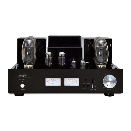
User bias control has been used for bias adjustment and two meters have been added to the front plate to allow you to monitor bias with ease. Bias meter here on LM-150IA is not just a meter for monitoring the bias but also a power level meter when switched to Meter by the selector on the front. -
Page 5: Specifications
Do not attempt to service this product yourself. Opening the cover may expose you to dangerous voltage or other hazards. Use only spare parts and accessories recommended by Line Magnetic. We are not responsible for any problems caused by checking and opening without permission of our company. For... -
Page 6: Recommendations
Electromagnetic Compatibility (2004/108/EC) and apply eco-design requirements for energy products (2009/125/EC) when the appliance is installed and used in accordance with the user manual. For continued compliance only Line Magnetic accessories must be used with this product and servicing must be performed by specialized and qualified staff. -
Page 7: Location And Precautions
Keep all packing materials for future use and please fill in the warranty card for registration of warranty. Your Line Magnetic product is covered by the legal warranty in force in your country. You may also have other rights which vary from country to country, state to state. -
Page 8: Functions Descriptions (Front View)
Functions descriptions Input voltage level of the amplifier is 240VAC ±5% and please, make sure that your local voltage is the same as indicated on the rear panel. A too low or too high voltage can cause serious damage to your amplifier. In case you find an improper voltage, please contact our company responsible for the power supply or your local dealer. -
Page 9: Functions Descriptions (Rear View)
Rear panel Signal input:Inputs (RCA plugs) are for connecting a digital line level source to your amplifier. It is designed to receive an analog signal (as opposed to digital signal). To connect your source we are using a traditional RCA cable, they are usually identified by a color code RED to the RIGHT channel WHITE to the LEFT channel. -
Page 10: Bias Adjustment (Top View)
Top view V1, V2, V3, V4: KT150 tubes V5 and V6: 6SN76EH tubes 12AX7 tube V8 and V9: 12AU7 tubes BIAS ADJ.: Bias adjustment screws for tubes V1 and V2. Bias Current: Allows to view the tube V1 bias level on the ampere meter when the small handle is down and when the handle is up, you can see the bias level on the ampere meter for the V2 tube. -
Page 11: Speaker Connection
Speaker connection WARNING: Make sure that the device is not plugged into the mains before making any connections. It is also recommended to turn off or disconnect all other devices associated while making connections to the product. Never operate the amplifier without having first connect the loudspeakers. The operation of a tube amplifier tube is different from transistor amplifier;... -
Page 12: Audio Connection
Audio connection Use a RCA (Cinch) stereo audio cable (red and white plugs) to connect your sources. 1- During installation please always refer to other product’s operation manuals. 2- Please do not insert the power cord into the main socket until all sources are connected. 3- R refers to the Right channel while L represents the Left channel. -
Page 13: Turning On
Line Magnetic Audio reserves the right to change specifications at any time without further notice in advance if products are upgraded. Specifications on the manual only show the specifications of the amplifier you’ve bought. -
Page 14: Remote Control
Remote control Volume + button to increases sound level - button to decreases sound level Mute: To silence the system Installation and replacement of the batteries Installation 1. Remove the screws of the remotes back cover. 2. Insert two 1,5V AAA batteries using the + and - indicators to insert them in the correct position. -
Page 15: Tube Replacement
Tube replacement Basics tubes Common replacements 12AX7 12AX7EH, ECC83, E83CC, CV4004, ECC803, 5751 12AU7 12AU7EH, ECC82, 5814, 6189, CV400 6SN7EH 6N8P, 6H8M, 6F8G, CV181, QB65, ECC32 KT150 KT120 Maintenance WARNING As a precaution, it is best to unplug the unit before handling and ensure the heat generated by the product has been properly dissipated. -
Page 16: Troubleshooting
IR sensor located on the The LM-150IA is designed and manufactured with our original parts to achieve the best results. Line Magnetic is not responsible for problems or damage caused by non-original parts being used in the unit. - Page 17 Line Magnetic Australia Pty Ltd Email: service@line-magnetic.com.au www.line-magnetic.com.au...
Need help?
Do you have a question about the LM-150IA and is the answer not in the manual?
Questions and answers