Table of Contents
Advertisement
www.tektone.com
Phone:
828.524.9967
Toll-Free:
800.327.8466
Sales:
Option 2
Tech Support:
Option 3
324 Industrial Park Road
Franklin, NC 28734
tektone@tektone.net
Fax: 828.524.9968
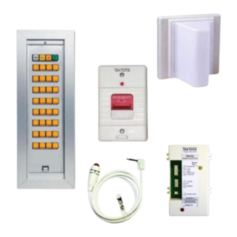
Tek-CARE
Visual Nurse Call Signaling System
Operation, Installation and Service Manual
The Tek-CARE
NC110 Visual Nurse Call Signaling System is designed for nursing
®
home or individual ward use. The nurse call system provides audible and visual
indication of all calls originating in the system, including both normal and emergency
calls. The NC110A and NC110N Master Stations contain lamps for call indication,
as well as tone-off switch and an audible tone signaling device.
NC110
®
UL
1069 Listed
®
IL381
SECTION E
Rev. 23 - 7/2017
Advertisement
Table of Contents

Subscribe to Our Youtube Channel
Related Manuals for TekTone Tek-CARE NC110


Summary of Contents for TekTone Tek-CARE NC110
- Page 1 IL381 SECTION E Rev. 23 - 7/2017 Tek-CARE NC110 ® Visual Nurse Call Signaling System 1069 Listed ® Operation, Installation and Service Manual www.tektone.com Phone: 828.524.9967 Toll-Free: 800.327.8466 Sales: Option 2 Tech Support: Option 3 The Tek-CARE NC110 Visual Nurse Call Signaling System is designed for nursing ®...
- Page 2 Operation, Installation and Service Manual No part of this publication may be copied without the express written permission of TekTone Sound & Signal Mfg., Inc. The Copyright © 2001–2017 TekTone Sound & Signal Mfg., Inc., All rights reserved. ® ®...
- Page 3 ..........IL381 Tek-CARE NC110 Manual • iii Copyright © TekTone Sound & Signal Mfg., Inc. All Rights Reserved. ®...
-
Page 4: Table Of Contents
......iv • IL381 Tek-CARE NC110 Manual ® Copyright © TekTone Sound & Signal Mfg., Inc. All Rights Reserved. -
Page 5: Figure 1-Nc110N Master Station Control Locations
6 – Lamp Test Button: Illuminates all lamps on panel when pressed. IL381 Tek-CARE NC110 Manual • 1 Copyright © TekTone Sound & Signal Mfg., Inc. All Rights Reserved. ® Drawing Name & Number: IL381 NC110N Product Rev0 121902 1... -
Page 6: Figure 2-Nc110A Master Station Control Locations
4 – Plug: Connects call cord to patient station when plugged into call cord jack. 5 – Call Button: Places a call when pressed, if cord is connected to patient station. 2 • IL381 Tek-CARE NC110 Manual ® Copyright © TekTone Sound & Signal Mfg., Inc. All Rights Reserved. - Page 7 Call a Nurse: Press the call button. The call placed lamp will illuminate to indicate Figure 4 call placement. Wait for the nurse. IL381 Tek-CARE NC110 Manual • 3 Copyright © TekTone Sound & Signal Mfg., Inc. All Rights Reserved. ®...
-
Page 8: Figure 4-Emergency, Code, Call & Duty Station Control Locations
6 – Call/Cancel Button: Places a call when pressed to in position. Cancels the call when pressed or twisted to out position. 7 – Tone Off Switch: Silences normal audible tone signal when pushed down. 4 • IL381 Tek-CARE NC110 Manual ® Copyright © TekTone Sound & Signal Mfg., Inc. All Rights Reserved. - Page 9 There are no user serviceable parts on the LI382LED Corridor/ Zone Lights. There are no user serviceable parts on the LI382 Corridor Zone Lights other than lamps and red bulb cover. IL381 Tek-CARE NC110 Manual • 5 Copyright © TekTone Sound & Signal Mfg., Inc. All Rights Reserved. ®...
- Page 10 • Annunciator lamps for call indication. • Additional operating controls, including tone off and tone test switches and additional emergency and normal call indicators. 6 • IL381 Tek-CARE NC110 Manual ® Copyright © TekTone Sound & Signal Mfg., Inc. All Rights Reserved.
- Page 11 Effective 7/2017, the SF339 has been discontinued. It is documented in this manual for reference purposes only. IL381 Tek-CARE NC110 Manual • 7 Copyright © TekTone Sound & Signal Mfg., Inc. All Rights Reserved. ®...
- Page 12 100’. PK153 Third Priority Conrol Unit: Locate the PK153 in the same location as the PK152 or PK151A Power & Control Unit. 8 • IL381 Tek-CARE NC110 Manual ® Copyright © TekTone Sound & Signal Mfg., Inc. All Rights Reserved.
- Page 13 Control Unit and the IH151N Junction Box to 117 VAC - 60 cycle power source. Do not connect power. Refer to for typical system wiring and cable sizes. Figure 11 Figure 12 IL381 Tek-CARE NC110 Manual • 9 Copyright © TekTone Sound & Signal Mfg., Inc. All Rights Reserved. ®...
-
Page 14: Figure 5-Master Panel Housing Chart And Wall Cut-Out Details
TekTone OH200-series. ® Surface Wall Mounting: Fasten box and frame assembly to wall through holes provided in back of box. Use suitable fasteners. Back box must be TekTone OH300-series. ® Figure 5—Master Panel Housing Chart and Wall Cut-Out Details 4″... - Page 15 If shorts or grounds are encountered, find and correct the problem before continuing. Make sure minimum number of conductors needed for all of the equipment being used in the system are available. IL381 Tek-CARE NC110 Manual • 11 Copyright © TekTone Sound & Signal Mfg., Inc. All Rights Reserved. ®...
- Page 16 LI150B, LI150N Duty Stations: Push the tone off switch up. 12 • IL381 Tek-CARE NC110 Manual ® Copyright © TekTone Sound & Signal Mfg., Inc. All Rights Reserved.
- Page 17 • On all LI150B Duty Stations, the call lamp should be flashing, and an intermittent audible call tone should be heard. The tone off button must not cancel the emergency call tone. IL381 Tek-CARE NC110 Manual • 13 Copyright © TekTone Sound & Signal Mfg., Inc. All Rights Reserved. ®...
-
Page 18: Figure 8-Nc110N Selector Lamp/Switch Lens, Filter And Lamp Replacement
Figure 8—NC110N Selector Lamp/Switch Lens, Filter and Lamp Replacement 1 – Lens 2 – Filter 3 – 24V Lamp 4 – Switch Knob 14 • IL381 Tek-CARE NC110 Manual ® Copyright © TekTone Sound & Signal Mfg., Inc. All Rights Reserved. - Page 19 For repair or replacement of any other parts, contact qualified service personnel. A list of replacement parts and numbers appears in the section. Replacement Parts IL381 Tek-CARE NC110 Manual • 15 Copyright © TekTone Sound & Signal Mfg., Inc. All Rights Reserved. ®...
- Page 20 LI382 Corridor Zone Lights SF301A Call Cord SF100C, SF100N, SF100/2, SF102 Call Stations SF302 Call Cord Dual SF100C, SF100N, SF100/2, SF102 Call Stations 16 • IL381 Tek-CARE NC110 Manual ® Copyright © TekTone Sound & Signal Mfg., Inc. All Rights Reserved.
-
Page 21: Figure 9-Block Wiring Diagram Without Zone Lamps
POINT WIRE DOME TRUNK & SERIES SERIES POINT WIRE STATION STATION Drawing Name & Number: IL381 NC110N Block Diagram 1 Rev0 062614 IL381 Tek-CARE NC110 Manual • 17 Copyright © TekTone Sound & Signal Mfg., Inc. All Rights Reserved. ®... -
Page 22: Figure 10-Block Wiring Diagram With Zone Lamps
SERIES POINT WIRE STATION STATION Drawing Name & Number: IL381 NC110N Block Diagram 2 Rev0 062614 NC110N Wiring Diagram with Zone Lamps 18 • IL381 Tek-CARE NC110 Manual ® Copyright © TekTone Sound & Signal Mfg., Inc. All Rights Reserved. -
Page 23: Figure 11-Nc110A Wiring Diagram
IL381 Tek-CARE NC110 Manual • 19 Copyright © TekTone Sound & Signal Mfg., Inc. All Rights Reserved. ®... - Page 24 20 • IL381 Tek-CARE NC110 Manual ® Copyright © TekTone Sound & Signal Mfg., Inc. All Rights Reserved.
-
Page 25: Figure 13-Nc150N, Nc200N, Two Stations In Parallel
IL381 Tek-CARE NC110 Manual • 21 Copyright © TekTone Sound & Signal Mfg., Inc. All Rights Reserved. ®... -
Page 26: Figure 14-Nc110A Housing Installation Diagram
NC110A TYPICAL INSTALLATION REV0 112806 1 Figure 15—PL116 Wall Plate Wiring Diagram PL116 REAR VIEW TO PK151 TO FIELD IL381 PL116 REAR VIEW REV2 021015 22 • IL381 Tek-CARE NC110 Manual ® Copyright © TekTone Sound & Signal Mfg., Inc. All Rights Reserved. -
Page 27: Figure 16-Nc110N Second Master Wiring Diagram
N (common) only. All other functions are supplied by the primary PK151A or PK152. Rev. 0 • 10/07/96 • MEL Rev. 1 • 05/24/10 • RLT Rev. 2 • 10/05/10 • RLT IL381 Tek-CARE NC110 Manual • 23 Copyright © TekTone Sound & Signal Mfg., Inc. All Rights Reserved. ®... -
Page 28: Figure 17-Pk153 Wiring Diagram
24 • IL381 Tek-CARE NC110 Manual ® Copyright © TekTone Sound & Signal Mfg., Inc. All Rights Reserved. -
Page 29: Figure 18-Pk153 Wiring Diagram With Sf156B Code Station
IL381 Tek-CARE NC110 Manual • 25 Copyright © TekTone Sound & Signal Mfg., Inc. All Rights Reserved. ®... -
Page 30: Figure 19-Pk152 Or Pk151A To Pk800A Interconnection
26 • IL381 Tek-CARE NC110 Manual ® Copyright © TekTone Sound & Signal Mfg., Inc. All Rights Reserved. -
Page 31: Figure 20-Sf337C Cross Reference Diagram
IL381 Tek-CARE NC110 Manual • 27 Copyright © TekTone Sound & Signal Mfg., Inc. All Rights Reserved. ®... -
Page 32: Figure 21-Sf339 Cross Reference Diagram
28 • IL381 Tek-CARE NC110 Manual ® Copyright © TekTone Sound & Signal Mfg., Inc. All Rights Reserved. -
Page 33: Figure 22-Nc110N Hookup To Nc150N, Nc200N
SELECTOR MODULE TERMINAL MODULE NC110N PK151A / PK152 SELECTIVE LAMP WIRE ON NC150N, NC200N IL381 NC110N NC150N NC200N Hookup Rev2 100110 1 IL381 Tek-CARE NC110 Manual • 29 Copyright © TekTone Sound & Signal Mfg., Inc. All Rights Reserved. ®... -
Page 34: Figure 23-Sf157 And Sf157/2 Wiring Diagram
30 • IL381 Tek-CARE NC110 Manual ® Copyright © TekTone Sound & Signal Mfg., Inc. All Rights Reserved.
Need help?
Do you have a question about the Tek-CARE NC110 and is the answer not in the manual?
Questions and answers