Advertisement
Quick Links
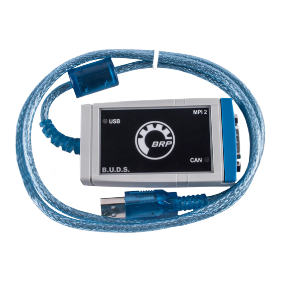
COMMUNICATION TOOLS AND
B.U.D.S.
SERVICE TOOLS
Description
MPI-2 DIAGNOSTIC CABLE..........................................................
MPI-2 INTERFACE CARD ..............................................................
SERVICE TOOLS – OTHER SUPPLIER
Description
MALE-FEMALE EXTENSION SERIAL CABLE...............................
GENERAL
PROCEDURES
Refer to
communication tools.
If communication problems occur, refer to
BLESHOOTING
in this subsection.
TROUBLESHOOTING
DIAGNOSTIC TIPS
IMPORTANT: Make sure all connections are
made and vehicle is powered up before starting
B.U.D.S. to allow proper communication between
the vehicle and B.U.D.S. software.
MPI-2 Connection Troubleshooting
MPI-2 Status Lights
The MPI-2 includes 2 status lights that indicate the
connection condition: USB and CAN. Both lights
must be GREEN for the MPI-2 to function prop-
erly. Otherwise, refer to the following charts.
vdd2006-001-151_b
Prerequisite for USB communication:
– PC Computer turned on
– MPI-2 connected to PC computer.
smr2014-026
Subsection XX (COMMUNICATION TOOLS AND B.U.D.S.)
for instructions on the
TROU-
Part Number
710 000 851 ............................................. 3
529 036 018 ......................................... 3–4
Part Number
DB9
............................................. 3
USB LIGHT
STATUS
– Check USB connection between
MPI-2 and PC computer.
Light is
– Check USB operation on PC
OFF
computer (hardware or Windows
drivers).
– Connections are GOOD.
Light is
Communication can take place
GREEN
on USB side.
Prerequisite for CAN communication:
– MPI-2 connected to diagnostic connector on ve-
hicle.
– Tether cord installed on the vehicle engine cut-
off switch.
– ECM turned on (momentarily press the START
button).
– B.U.D.S. started and logged on.
CAN LIGHT
STATUS
Light is
Check connection between MPI-2 and
OFF
diagnostic connector on vehicle.
Light is
Check CAN wires/connectors on
RED
vehicle.
Connections are GOOD.
Light is
Communication can take place on
GREEN
CAN side.
Page
Page
WHAT TO DO
WHAT TO DO
1
Advertisement

Subscribe to Our Youtube Channel
Related Manuals for BRP MPI-2

Summary of Contents for BRP MPI-2
- Page 1 MPI-2 Status Lights – ECM turned on (momentarily press the START button). The MPI-2 includes 2 status lights that indicate the – B.U.D.S. started and logged on. connection condition: USB and CAN. Both lights must be GREEN for the MPI-2 to function prop- CAN LIGHT erly.
-
Page 2: Troubleshooting
NOTE: The tether cord cap must be installed on avoid engine starting. the engine cut-off switch. 5. Continue with the procedure undertaken prior 3. Ensure both USB and CAN lights on the MPI-2 to the appearance of the message box. MPI-2 CONNECTION are GREEN. Refer to... - Page 3 PROCEDURES MULTI-PURPOSE INTERFACE-2 (MPI-2) The MPI-2 (Multi-Purpose Interface-2) in conjunc- tion with the MPI-2 diagnostic cable is used with B.U.D.S. software to communicate with the ECM (engine control module) and other modules. MPI-2 Power The MPI-2 interface card uses the power from the PC computer USB port.
- Page 4 5. Read electronic modules by clicking the Read Data button. mmr2006-079-200 MPI-2 INTERFACE CARD CONNECTED TO USB PORT CAUTION If the computer you are using is connected to a power outlet, there is a poten- tial risk of electric shock when working in con- tact with water.
- Page 5 Subsection XX (COMMUNICATION TOOLS AND B.U.D.S.) Electronic Modules ECU Update 2. If the Update option is black, an update file is available for this module. NOTICE Failure to strictly follow a procedure to update a module may permanently damage the module. Whenever B.U.D.S.
- Page 6 Subsection XX (COMMUNICATION TOOLS AND B.U.D.S.) NOTE: When selecting the update menu in 2. Remove tether cord from the engine cut-off B.U.D.S., a dialog box will appear and the update switch. file description may give some clue to finding the Disconnect MPI connections and secure the vehi- vehicle-related information in BOSSWeb.
Need help?
Do you have a question about the MPI-2 and is the answer not in the manual?
Questions and answers