Table of Contents
Advertisement
Quick Links
GAMMA instabus
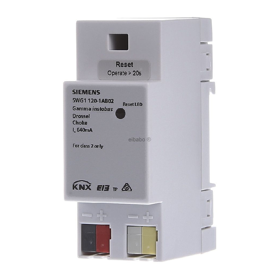
Drossel N120/02
5WG1 120-1AB02
Choke N120/02
Bedien- und Montageanleitung
Operating and Mounting Instructions
Stand: April 2005
Issued: April 2005
Bus
L1 N Erde
Verbinder
N 191
AC 120...230 V
Spannungs-
versorgung N 125/01
N 125/11
Linien-/ Bereichs-
ko ppler N 140/3
Bus
DC 24 V
Spannungs-
L1 N Erde
ve rsorgung
AC 120...230 V
N 125/21
Linien-/ Bereichs-
koppler N 140/3
Datenschiene:
äußere Leiterbahnen:
DC 24V
innere Leiterbahnen:
Buslinie
Bild / Figure 1
Produkt- und Funktionsbeschreibung
Zur Versorgung der Busteilnehmer wird die notwendige Versor-
gungsspannung zusammen mit den Datentelegrammen auf ei-
ner gemeinsamen Leitung übertragen.
Die Drossel N 120/02 verhindert den Kurzschluß der Datentele-
gramme auf der Buslinie durch die Versorgungsspannung. Sie
erhält die DC 29V Versorgungsspannung über die Kleinspan-
nungsklemme (weiß-gelbe Klemme). Die Versorgungsspannung
wird auch an die beiden äußeren Leiterbahnen der Datenschie-
ne weiterleitet und wird über Induktivitäten auf die beiden in-
neren Leiterbahnen und die Busklemme (schwarz-rote Klemme)
gespeist.
Die Versorgungsspannung kann über die Kleinspannungsklem-
me (weiß-gelbe Klemme) von der Spannungsversorgung
N 125/21 auf die beiden äußeren Leiterbahnen der Datenschie-
ne eingespeist werden.
Durch den eingebauten Resetschalter (Betätigung > 10s) wer-
den die Busteilnehmer in den Grundzustand gesetzt, d.h. nach
dem Wiedereinschalten nehmen die Busteilnehmer ihren vor-
gegebenen Grundzustand ein. Dabei wird die Buslinie kurzge-
schlossen und die Versorgungsspannung abgeschaltet.
Für die Gleichspannung der Versorgungsspannung ist der Dros-
selwiderstand niederohmig. Da die Informationen über den
instabus EIB in Form einer Wechselspannung übertragen wer-
den, ist die Drossel N 120/02 für sie hochohmig. Dadurch stellt
die Versorgungsspannung nur eine geringe Belastung für das
Informationssignal dar.
Weitere Informationen
http://www.siemens.de/gamma
instabus EIB
Linie 0
Anschlussbeispiel
(Hauptlinie)
Datenschiene:
siehe Bild 1
äußere Leiterbahnen:
frei
innere Leiterbahnen:
Buslinie
Technische Daten
Eingangsspannung
Linie 1
• Bemessungsspannung: DC 29 V (DC 28...30V)
• Bemessungsstrom: 640 mA
Anschlüsse
• Spannungsversorgung:
Linie 1
Verbinder
- Druckkontakte auf Datenschiene (äußere Leiterbahnen)
REG 191/01
- Kleinspannungsklemme (gelb-weiss), schraubenlos
Datenschiene:
äußere Leiterbahnen:
0,6...0,8mm Ø eindrähtig
frei
innere Leiterbahnen:
• Buslinie:
Buslinie
- Druckkontakte auf Datenschiene (innere Leiterbahnen)
- Busklemme (schwarz-rot), schraubenlos
0,6...0,8mm Ø eindrähtig
Mechanische Daten
DC 24 V
(Verbindung zu
• Abmessungen: Reiheneinbaugerät im N-Maß,
DC 24V von N 125/21)
Breite 2 TE (1 TE = 18 mm)
Linie 2
• Gewicht: ca. 100 g
Drossel
N 120/02
Elektrische Sicherheit
• Schutzart (nach EN 60529): IP 20
Umweltbedingungen
• Klimabeständigkeit: EN 50090-2-2
• Umgebungstemperatur im Betrieb: - 5 ... + 45 °C
• Lagertemperatur: - 25 ... + 70 °C
• rel. Feuchte (nicht kondensierend): 5 % bis 93 %
D
Seite 1 von 2
GB
Product and Applications Description
The operating voltage for the bus devices supplied through the
bus is transmitted via the same twisted pair cable as the data
telegrams.
The choke N 120/02 prevents the DC 29V power-supply from
short-circuiting the data telegram on the bus line. The choke re-
ceives the power via the low-voltage connector (yellow-white)
on the front side. This power is directly connected to the two
outer printed conductors of the data rail. It is fed via inductors
to the two inner printed conductors of the data rail and to the
bus connector terminal (black-red) on the front side of the de-
vice.
The DC 29V supply voltage fed to the low-voltage connector
(yellow-white) may be sourced from a power supply unit
N 125/21. It may also be sourced from a power supply N123 via
the data rail.
Via the built-in reset-switch (operation > 10 s) the bus devices
are set to their default setting, i.e. the bus devices return to
their default setting with the recurring supply voltage. This is
done by short-circuiting the bus line and switching off the sup-
ply voltage.
To the DC 29V supply voltage the choke resistance is
low. To the data signal transmitted on instabus EIB, which is an
alternating current, the resistance of the choke N 120/02 is high
and therefore the operating voltage supply does not signifi-
cantly affect the information signal.
Additional Information
http://www.siemens.com/gamma
Example of Operation
see figure 1
Technical Specifications
Input voltage
• rated voltage: DC 29 V (DC 28...30V)
• rated current: 640 mA
Connections
• power supply:
- pressure contacts on data rail (outer printed conductors)
- screwless extra low voltage terminal (yellow-white)
∅ 0,6 ... 0,8 mm, solid single-core copper wire
• bus line:
- pressure contacts on data rail (inner printed conductors),
- screwless extra low voltage terminal (red–black)
∅ 0,6 ... 0,8 mm, solid single-core copper wire
Physical specifications
• N-system DIN-rail mounted device,
width: 2 SUs (1 SU = 18 mm)
• weight: approx. 100 g
Electrical safety
• protection (according to EN 60529): IP 20
Environmental specifications
• climatic conditions: EN 50090-2-2
• ambient temperature operating: - 5 ... + 45 °C
• ambient temperature non-op.: - 25 ... + 70 ° C
• relative humidity (non-condensing): 5 % to 93 %
page 1 of 2
2515044115
DS 01
Advertisement
Table of Contents

Related Manuals for Siemens 5WG1 120-1AB02


Summary of Contents for Siemens 5WG1 120-1AB02
- Page 1 The operating voltage for the bus devices supplied through the Zur Versorgung der Busteilnehmer wird die notwendige Versor- Drossel N120/02 5WG1 120-1AB02 bus is transmitted via the same twisted pair cable as the data gungsspannung zusammen mit den Datentelegrammen auf ei- telegrams.
- Page 2 • Die Bedienungsanleitung ist dem Kunden auszuhändigen. • The operating instructions must be handed over to the client. • Ein defektes Gerät ist an die zuständige Geschäftsstelle der • Any faulty device should be returned to the local Siemens of- Siemens AG zu senden. fice.
Need help?
Do you have a question about the 5WG1 120-1AB02 and is the answer not in the manual?
Questions and answers