
Related Manuals for Hommy HM116T


Summary of Contents for Hommy HM116T
- Page 1 Model: ______________ Date: ______________ S/N: ______________ (Please read the manual carefully before operating the machine.)
- Page 2 Note: In order to protect the operator from injury, external power source of ice cream machine must be connected to the earth leakage circuit-breaker. See the picture below. Air-cooled machine When installed indoors, the machine should be placed far Please leave a space about 50cm at least from sprinkler heads and around the machine, this will make the air wetness, otherwise it will result in severe...
- Page 3 Note: The following steps should be carried out by professional repair technicians. When phase reversal happens on power supply, two of the live wires”L1” and “L” should be exchanged to install. Important note: Violating the safety regulations may result in heavy casualties.
- Page 4 ●Do allow untrained persons operate Be careful when you machine. disassemble the agitating ●Before disconnect the power supply, do shaft (disconnect the power not disassemble the throat block, the supply before the operation), agitating shaft or transmission shaft. otherwise it may cause injury. ●Do not dive objects or fingers into the throat block discharge outlet.
- Page 5 when the voltage is between 220 volts and 240 volts, which can ensure steady stream of electricity. According to the large starting current, the electric current should load the power capacitance. c) The cross-sectional area of power line must be larger than 2.5 square millimeters when the machine is volts,which can ensure steady stream of electricity.
-
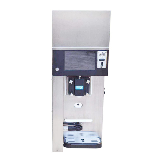
Page 6: Machine Structure
MACHINE STRUCTURE Ref. No. Description Quantity Ref. No. Description Quantity Converter electricity box Left rear corner post Stirring shaft Hopper lid Long push rod Mixer Material collecting trough Gravity pipe Material collecting tray Switch Cone holder Short push rod Lid of material collecting tray Advertising screen Rubber feet Coin accepter... - Page 7 Overall dimensions(see the picture below) Technical parameters model Dimension (mm) Net weight (Kgs.) HM116 769×403×1080 Electrical parameters model voltage Rated current(MIN) power Single phase, HM116 three-wine system, 1500W 220V/ 50Hz, Brush package + attachment Clean the transmission shaft sleeve, blanking stopper and blanking outlet.
- Page 8 Clean the throat block. Clean the cylinder. Clean the hopper and outlet of throat block. Lube. Installation sketch of top board Ref. No. Description Quantity Hopper lid Air outlet Mixer...
- Page 9 Liquid-level sensor Top board Advertising screen Gravity pipe Gravity pipe instruction After the hopper is cleaned, lube should be cover the sealing rings of expansion tube and then the expansion tube is installed in the blanking hole of hopper. The air intake on expansion tube is adjustable as needs: φ4, φ6, and φ8.
- Page 10 Module’s disassembly and installation The structure diagram and installation of stainless steel stirring shaft Ref. No. Description Quantity Throat block Shaft core Locating sleeve Sheath A for front scrapper Stainless steel stirring shaft Plastic scrapper Sheath B for front scrapper When you install the stirring shaft, two orifices of plastic scrapper should be positioned to the locks and pressed in.
- Page 11 Installation and disassembly of stainless steel stirring, transmission shaft and sealing gasket Ref. No. Description Quantity Throat block Fixing bolt Locating sleeve...
- Page 12 Sheath B of stirring shaft Sheath A of stirring shaft Stainless steel stirring shaft Plastic scrapper Transmission shaft module Installation steps of stirring shaft 1、Stirring shaft installation a, transmission shaft b, sealing gasket c, plastic sleeve 1-1)Before stirring shaft installation, the surface of transmission shaft and plastic sleeve must be covered evenly with lube , but sealing gasket must be covered on...
- Page 13 turn.(see chart, right) Note: In installation, the bulge side of the plastic sleeve must toward transmission shaft. 1-3)Insert the transmission shaft module into the coupling. In installation, rolling the module left and right is to aim at the hole of the coupling. And the shaft end should be inserted into the coupling.
- Page 14 Usage(Installation after cleaning) 1. Install the stirring shaft Push the stirring shaft into the cylinder, to ensure the stirring shaft is located above the transmission shaft position, then rotate slightly the stirring shaft, until it is placed in the correct position. If installed correctly, the stirring shaft will no extend to the cylinder.
- Page 15 3.When ensuring that the machine stops, you clean the hopper with towel. 4.Put a bucket under the outlet of throat block and then click on cleaning icon to drain away water. Note: do not click on refrigeration button when clean the machine. Usage(Disinfection) Step 1 : Prepare a few qualified disinfectant, use warm water and follow the...
- Page 16 Step 3 : Clean the hopper with towel or brush. Step 4 : Clicking on cleaning button is to make the disinfectant circulated, which must be 5 minutes at least. Step 5 : Put a bucket under the outlet of throat block and pull down the handle to drain away water.
- Page 17 Step 1 : pour the fresh ice cream slurry into hopper. Step 2: Install the gravity pipe and close the hole of gravity pipe. You put a measuring glass on the bottom of the throat block , then you pull down the handle to let the slurry flow into the measuring glass.
- Page 18 Step 2 : click on pasteurization icon, the machine entry the pasteurization program. Heating treatment consists of three stages: heating, heat preservation and freshness preservation. Do not remove the parts and feed the slurry when it is heating, because the slurry is very hot and heavy pressure is in cylinder.
-
Page 19: General Maintenance
Step 3: clean the bearing housing in the back of cylinder with brushes. Step 4: wipe all the outside surface of the machine with clean and disinfected towel. In cleaning and disinfection, you must be strictly followed to cleaning and disinfection schedule which is put forward by the local administrative department. - Page 20 Feature Instruction Feature Instruction Produce ice cream Cylinder mixing Pre-cooling Stop Heat treatment (Pasteurization) Defrost Drop down the left plunger Lift up the left plunger tappet tappet Lift up the cone tray tappet Drop down the cone tray tappet Test icon for producing ice Stop tappet running cream...
- Page 21 Operating instructions (Figure 1) 1、After the machine power on, and keyboard displays the interface (Figure 1): (Figure 2) 2、Press 3 times the key (Figure 1), and enter into the interface (Figure 2). The initial password: “admin” and “user” (Note: Password "admin" have permission to enter the menu of machine work mode, sell record, sell set, machine set;...
- Page 22 (Figure 3) 3、After input password, then press the key “OK” to enter the interface (Figure 3), to run the procedure of cleaning, ice cream production, pre-cooling, heat treatment (Pasteurization), manual control running plungers and tappets, parameter setup, and etc. 1)Production ( with gravity pipe) Firstly, removing the gravity pipe and the slurry flow into the cylinder.
- Page 23 After production, click on the icon into the picture below Click on the ice cream icon and select one of mode to pay. Put in the coins or scan the QR code, there will be a icon “OK” on the screen. Put the cup on the holder and click on the icon”OK”...
- Page 24 (2)Clicking on the sales record, you can see the past sales and business volume. Figure4 (3)Clicking on sales setting, you can set the sales mode,the weight of ice cream and topping and the quantity of coins the customers should pay for. Figure 5 (4)clicking on machine setting, you can set the hardness of ice cream and the temperature of pre-cooling mode.
-
Page 25: Correct Usage
Error code instruction Error code Cause treatment Check the compressor and thermal Compressor is overloaded. relay. Motor is overloaded. Check the motor and thermal relay. Refrigeration pressure is too high. Check the refrigeration system The temperature sensor of hopper is Check the connector and the wire of faulty. - Page 26 the fixing nuts of throat block are it cause leaking slurry from tighten the fixing nuts not tightened. the side of throat block. click on the refrigeration icon the water is frozen in the do not click on the refrigeration icon when the cylinder is full of water.
-
Page 27: Troubleshooting Guide
Troubleshooting guide (1): Trouble Possible cause Solution The machine doesn’t ①Lack phase sequence. ① check the power supply and work and the screen ② stirring shaft’s negative direction wires displays error rotation ②、③replace the parts. code”E8” ③main circuit board doesn’t work. Stirring motor does... - Page 28 Troubleshooting guide (2): ● Trouble Possible cause Solution the machine ①leak refrigerant ① repair the leak and fill in ②refrigerant is not enough. refrigerant according refrigerate ③compressor is broken. nameplate parameter. ④ the sensors for cylinder and hopper are ②fill in moderate refrigerant broken.
- Page 29 light flickers leak slurry ①annual gasket is worn-out. ①~④replace the parts from ②the bearing is worn-out. ⑤tighten the nuts bearing ③the bearing sleeve is worn-out. ⑥ Remove the gear reducer, main stirring ④sealing gasket is worn-out. shaft and connecting shaft, and shaft ⑤fixing nuts of bearing are loose.
- Page 30 Troubleshooting guide (3): Trouble Possible cause Solution leak slurry ①the nuts of throat block are loose. ①tighten the nuts from throat ②the installation of throat block is incorrect. ② tighten the two nuts on a block ③O-gasket of throat block comes off diagonal ④O-gasket of throat block is worn-out.
-
Page 31: Circuit Diagram
Circuit Diagram... - Page 32 Spare parts 3 months 6 months 1 year Lamina in air pump ● Sealing o-ring for side plug ● Sealing gasket for center plug ● Sealing gasket in the back of throat As needs block Sealing gasket for transmission shaft ●...
Need help?
Do you have a question about the HM116T and is the answer not in the manual?
Questions and answers