
Related Manuals for peerless-AV SmartMount ST16D


Summary of Contents for peerless-AV SmartMount ST16D
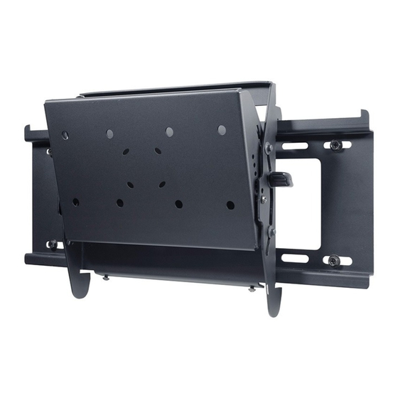
- Page 1 Installation and Assembly: Dedicated Tilt Wall Mount Model: ST16D Max Load Capacity: 200 lb (91 kg) 2300 White Oak Circle • Aurora, Il 60502 • (800) 865-2112 • Fax: (800) 359-6500 • www.peerlessmounts.com ISSUED: 09-15-05 SHEET #: 202-9031-3 08-18-11...
-
Page 2: Table Of Contents
Note: Read entire instruction sheet before you start installation and assembly. WARNING • Do not begin to install your Peerless product until you have read and understood the instructions and warnings contained in this Installation Sheet. If you have any questions regarding any of the instructions or warnings, please call Peerless customer care at 1-800-865-2112. -
Page 3: Parts List
Before you begin, make sure all parts shown are included with your product. Parts List Description Qty Part # A tilt bracket assemby 200-0936 B wall plate 200-1797 C #14 x 2.5" wood screw 5S1-015-C03 D concrete anchor 590-0320 E M10 x 15 mm socket head screw 520-9262 F 4 mm security allen wrench 560-1146... -
Page 4: Installation To Single Stud Wall
Installation to Single Wood Stud Wall WARNING • Installer must verify that the supporting surface will safely support the combined load of the equipment and all attached hardware and components. • Tighten wood screws so that wall plate is fi rmly attached, but do not overtighten. Overtightening can damage the screws, greatly reducing their holding power. -
Page 5: Installation To Double Wood Stud Wall
Installation to Double Wood Stud Wall WARNING • Installer must verify that the supporting surface will safely support the combined load of the equipment and all attached hardware and components. • Tighten wood screws so that wall plate is fi rmly attached, but do not overtighten. Overtightening can damage the screws, greatly reducing their holding power. -
Page 6: Installation To Solid Concrete Or Cinder Block
Installation to Solid Concrete or Cinder Block WARNING • When installing Peerless wall mounts on cinder block, verify that you have a minimum of 1-3/8" of actual concrete thickness in the hole to be used for the concrete anchors. Do not drill into mortar joints! Be sure to mount in a solid part of the block, generally 1"... -
Page 7: Attaching Plp Adapter Plate To Tilt Bracket Assembly
Note: Refer to accompanying instruction sheet for attachment of adapter plate to screen before proceeding with step 2. Attaching PLP Adapter Plate to Tilt Bracket Assembly Attach adapter bracket to interface bracket of tilt bracket assembly (A) using four M10 screws (E). Note: Full tilt bracket assembly not shown for clarity. -
Page 8: Attaching Lc Adapter Plate To Tilt Bracket Assembly
Note: Refer to accompanying instruction sheet for attachment of adapter plate to screen before proceeding with step 2. Attaching LC Adapter Plate to Tilt Bracket Assembly To prevent scratching the screen, set a cloth on a fl at, level surface that will support the weight of the screen. Place screen face side down. -
Page 9: Mounting And Removing Flat Panel Screen
Mounting and Removing Flat Panel Screen Hook tilt bracket assembly (A) onto wall plate (B). Then slowly swing screen in as shown. To lock the screen down, tighten security screw to wall plate using security allen wrench (F) as shown in detail 1. If mount is attached to double wood stud, solid concrete, or cinder block wall, screen can be adjusted horizontally if desired. -
Page 10: Adjusting The Tilt Angle Of The Flat Panel Screen
Adjusting the Tilt Angle of the Flat Panel Screen fi g 4.1 Adjust tension knob on right side of mount shown in detail 2 to desired tension to balance your screen size and weight. Push or pull from top or bottom of screen to adjust tilt as shown in fi... - Page 11 LIMITED FIVE-YEAR WARRANTY Peerless Industries, Inc. (“Peerless”) warrants to original end-users of Peerless® products will be free from defects in material and workmanship, under normal use, for a period of fi ve years from the date of purchase by the original end-user (but in no case longer than six years after the date of the product’s manufacture). At its option, Peerless will repair or replace, or refund the purchase price of, any product which fails to conform with this warranty.
Need help?
Do you have a question about the SmartMount ST16D and is the answer not in the manual?
Questions and answers