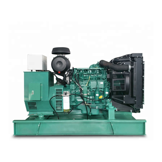
Volvo Penta TD520GE Workshop Manual

Volvo Penta TD520GE Workshop Manual

Industrial engines
Hide thumbs Also See for TD520GE:

Advertisement

TD520GE, TAD520GE, TD520VE, TAD520VE,
TAD530/531/532GE, TD720GE, TAD720GE, TD720VE,
TAD720VE, TAD721GE, TAD721VE, TAD722GE,
TAD722VE, TAD730/731/732/733GE
Safety information ................................................ 2
General information ............................................. 5
Repair instructions ............................................... 6
Special tools ........................................................ 9
Engine description ............................................... 12
Identification plates ............................................. 12
Engine serial number .......................................... 13
Cylinder numbering ............................................. 13
Engine, location of components .......................... 14
Starter motor side ............................................... 14
Service side ........................................................ 15
Lubrication system .............................................. 16
Fuel system ........................................................ 17
Commencement of delivery, Fb .......................... 18
Cooling system ................................................... 19
Technical data ...................................................... 20
Engine ................................................................ 20
Tables ................................................................. 22
Checks and adjustments ..................................... 30
Compression test ................................................ 30
Injectors, checking/adjusting ............................... 31
Disassembly, complete engine ........................... 33
Exposure of engine ............................................. 33
Fitting of fixture ................................................... 34
Engine, disassembly ........................................... 36
Assembly, complete engine ................................ 48
Engine, assembly ............................................... 48
Workshop Manual
Industrial Engines
Contents
Checks and adjustments ..................................... 82
Engine block ....................................................... 82
Crankshaft, measuring ........................................ 84
Connecting rods, measuring ................................ 87
Pistons ............................................................... 90
Camshaft ............................................................ 93
Camshaft bearings .............................................. 95
Cylinder head ...................................................... 97
Valve seat, changing .......................................... 100
Valve seat, grinding ............................................ 101
Valves, grinding .................................................. 101
Rocker arm bracket ............................................. 102
Control rod .......................................................... 103
Repairing components ........................................ 107
Group 21:
Flywheel ring gear, changing ............................... 107
Valve clearance, checking/adjusting ................... 109
Drive belts, adjusting and replacing ..................... 115
Group 22:
Reduction valve, removing .................................. 116
Reduction valve, inserting ................................... 116
Front housing, oil pump ....................................... 117
Engine oil cooler ................................................. 119
Lubricating oil pressure ....................................... 121
Group 23:
Changing injection pump ..................................... 123
Group 25:
Boost pressure .................................................... 124
Group 26:
Coolant pump ...................................................... 125
Thermostat ......................................................... 127
Wiring diagrams ................................................... 128
Index ..................................................................... 133
1

Advertisement

Table of Contents
loading

Summary of Contents for Volvo Penta TD520GE

  • Page 1: Table Of Contents

    Workshop Manual Industrial Engines TD520GE, TAD520GE, TD520VE, TAD520VE, TAD530/531/532GE, TD720GE, TAD720GE, TD720VE, TAD720VE, TAD721GE, TAD721VE, TAD722GE, TAD722VE, TAD730/731/732/733GE Contents Checks and adjustments ........82 Safety information ..........2 Engine block ............82 Crankshaft, measuring ........84 General information ..........5 Connecting rods, measuring ........
  • Page 2: General Information

    General information Group 20 Engine description Location of the engine identification plate Each engine is supplied with two identical identifica- tion plates, of which one is mounted on the right side of the cylinder block and the other one should be mou-nted in a suitable location adjacent to the engine.
  • Page 3: Engine Serial Number

    Group 20 General information Engine serial number The engine serial number is stamped into the engine block and engine identification plate. The serial number is a ten-digit number. Only the last eight digits are stamped into the engine block. Cylinder numbering (A = flywheel)
  • Page 4: Engine, Location Of Components

    General information Group 20 Engine, location of components Starter motor side 1 Turbocharger 2 Lifting eye 3 Engine speed governor* 4 Rotation direction (counter-clockwise) 5 Flywheel housing 6 Flywheel 7 Starter motor 8 Coolant outlet pipe * Governor (Heinzmann) The governor for T(A)D 520, 530/532/720-722, 730-733GE/ VE series engines is a mechanically variable speed governor with a Heinzmann centrifugal measuring unit.
  • Page 5: Service Side

    Group 20 General information Service side 1 Oil filler cap 2 Coolant inlet pipe 3 Coolant pump 4 Alternator 5 Crankshaft pulley 6 Fuel pump 7 Fuel filter 8 Lubricating oil filter 9 Oil sump 10 Oil dipstick 11 Lubricating oil cooler 12 Power socket for hydraulic pump, air compressor etc.
  • Page 6: Lubrication System

    General information Group 20 Lubrication system 1 Oil pressure sender 2 Valve tappet with rocker arm lubrication 3 Oil suction pipe 4 Rocker arm 5 Return to oil sump 6 Spray nozzle for piston cooling 7 Oil channel to piston cooling nozzle 8 Lubricating oil cooler 9 Lubricating oil pump 10 Safety valve (pressure regulating valve)
  • Page 7: Fuel System

    Group 20 General information Fuel system 1 Fuel tank 2 Line to fuel pump 3 Fuel pump 4 Line to fuel filter 5 Fuel filter 6 Fuel line to fuel duct 7 Injection pump 8 Delivery pipe to injector 9 Injector 10 Fuel return line 11 Overflow valve with air ventilation screw 12 Return line to fuel tank...
  • Page 8: Commencement Of Delivery, Fb

    General information Group 20 Commencement of delivery, Fb The engine is equipped with a separate injection pump for each cylinder. This means that the commencement of delivery, Fb, when necessary, has to be adjusted separate for each pump unit. The com- mencement of delivery, Fb, is adjusted with a shim, placed between lifter and injection pump.
  • Page 9: Cooling System

    Group 20 General information Cooling system 1 Coolant connection (inlet) 2 Thermostat housing 3 Coolant pump 4 Lubricating oil cooler 5 Cylinder cooling 6 Cylinder head cooling 7 Coolant connection (outlet)
  • Page 10: Technical Data

    Technical data Group 20 Technical data Engine Engine TD 520GE TAD 520GE Engine weight, according to DIN 70020–A ....Approx. 550 kg (1212 lbs) Approx. 575 kg (1268 lbs) Engine displacement ..........4760 cm (290.4 in 4760 cm (290.4 in Bore ................
  • Page 11 Group 20 Technical data Engine TD720GE TAD720GE Engine weight, according to DIN 70020–A ....ca. 750 kg (1653 lbs) ca. 760 kg (1676 lbs) Engine displacement ..........7150 cm (436.3 in 7150 cm (436.3 in Bore ................108 mm (4.25”) 108 mm (4.25”) Stroke ...............
  • Page 12: Tables

    Technical data Group 20 Engine TD720VE TAD720/721/722VE Engine weight, according to DIN 70020–A ....ca. 570 kg (1257 lbs) ca. 572 kg (1261 lbs) Engine displacement ..........7150 cm (436.3 in 7150 cm (436.3 in Bore ................108 mm (4.25”) 108 mm (4.25”) Stroke ...............
  • Page 13 Group 20 Technical data Coolant Volvo Penta glycol (antifreeze) mixed 45/55 with clean water Anti-corrosion agent Used only in markets where there is no risk of freezing, mixed with water The anti-corrosion agent must not be mixed with glycol or other types of anti-corrosion fluid as this could result in negative consequences.
  • Page 14 Technical data Group 20 Tightening torque These tightening torques apply to oiled bolts and nuts. Parts that have been degreased (washed) should be oiled before they are fitted. Special tightening torque’s Nm / angle tightening (lbf.ft) Group 21 Engine Engine mounting ............ (192 lbf.ft) Starter motor ............
  • Page 15 Group 20 Technical data Tightening torques Nm / angle tightening (lbf.ft) Group 22 Oil system (±2) ±1.5 Oil cooler, screws ..........(15.5 lbf.ft) Oil cooler, hollow screw Step 1: ..............(59 lbf.ft) Step 2: ..............(118 lbf.ft) Oil cooler, screw plug ..........(59 lbf.ft) Front/oil pump housing ...........
  • Page 16 Technical data Group 20 Determination of shim thickness when changing the injection pump. Mathematical formula for new shim thickness: T = Ek - (L + A/100) → → → → → T Actual shim thickness, S , can be found in Table 2. S NOTE! This formula is applicable when changing the injection pump ONLY.
  • Page 17 Group 20 Technical data Determination of shim thickness when the injection valve opens Performed when replacing engine block, camshaft, or roller tappet. Mathematical formula for the new shim thickness: = L-[(Fb - Fb )x Vh + Vh + A/100)] korr →...
  • Page 18 Technical data Group 20 Determination of the corrected fitting size, E , and EP code for an injection pump. NOTE! When you change the engine block camshaft or roller tappet, you must determine the corrected fitting measurement, E , and change the relevant EP code on the engine identification plate. Mathematical formula for the corrected fitting size, E = L - [(Fb - Fb...
  • Page 19 Group 20 Technical data Table 2 Theoretical Theoretical Shim thickness Shim thickness thickness thickness “S ” (mm) “S ” (mm) “T ” (mm) “T ” (mm) 0.95–1.049 3.05–3.149 1.05–1.149 3.15–3.249 1.15–1.249 3.25–3.349 1.25–1.349 3.35–3.449 1.35–1.449 3.45–3.549 1.45–1.549 3.55–3.649 1.55–1.649 3.65–3.749 1.65–1.749 3.75–3.850 1.75–1.849...
  • Page 20: Checks And Adjustments

    Checks and adjustments Group 20 Checks and adjustments Compression test (21002) Special tools: Adapter for compression testing ....999 8694 Compression gauge ........998 8539 The injectors have been removed, the valve clearance has been checked. 1. Fit adapter 999 8694. 2.
  • Page 21: Injectors, Checking/Adjusting

    NOTE! Let an authorized workshop do the tests and adjustments. The test requires equipment not sold by AB Volvo Penta. WARNING! Be very careful when working with the fuel injector nozzle. The fuel pressure jet can penetrate deep into the skin tissue and cause blood poisoning.
  • Page 22 Checks and adjustments Group 20 The order for removing parts is: 1 Cap nut 2 Injection nozzle 3 Adapter 4 Pressure pin 5 Compression spring 6 Shim 8. Set the pressure by selecting an appropriate shim. (A thicker shim increases the opening pres- sure.) Tighten the cap nut to 40 ±5 Nm (33 ±3.7 lbf ft).
  • Page 23: Disassembly, Complete Engine

    Group 21 Disassembly, complete engine Disassembly, complete engine Special tools: Stand for mounting engine (Unit stand) ..998 6485 Engine fixture ..........999 8671 Puller ............999 6400 Socket for injector removal ......999 8007 Filter wrench ..........999 9179 Pressure tool (control rod) ......
  • Page 24: Fitting Of Fixture

    Disassembly, complete engine Group 21 5. Remove tha alternator as well as extra power sources, alternator belt and bracket, see “Drive belts, adjusting and replacing”. Fitting of fixture Turbo charger, remove 1. Remove the oil pressure pipe, oil return pipe, and charger air pipe.
  • Page 25 Group 21 Disassembly, complete engine 3. Plug (1) the turbo and the connections for the oil return and the oil pressure pipes in the engine block. 4. Attach the engine bracket 999 8671 (1) to the engine and tighten to 25 Nm (18.5 lbf ft). NOTE! Use the accompanying screws, since their strength is higher than that of standard screws.
  • Page 26: Engine, Disassembly

    Disassembly, complete engine Group 21 Engine, disassembly 1. Remove the oil-trap housing for the crankcase ven- tilation (see picture). 2. Catch any remaining oil and dispose of it in accordance with the environmental regulations. 3. Loosen the fuel hose between filter and fuel pump.
  • Page 27 Group 21 Disassembly, complete engine 5. The starter motor can be removed at this stage, but it is easier to leave it on and remove it together with the transmission cover. 6. Remove the engine speed governor. Use a Torx socket E 10 (for electronic governors, use Allen key 6).
  • Page 28 Disassembly, complete engine Group 21 9. Remove the coolant pump and coolant housing, according to one of the pictures, depending on coolant pump model. The lower model is removed with 7 screws. First remove the bearing bracket for the intermediate pulley.
  • Page 29 Group 21 Disassembly, complete engine 12. Remove the delivery pipes, complete with the rub- ber seals. NOTE! Cover the injector and injector pump openings. 13. Remove the stop solenoid (alternatively the plug if the governor is electronic). NOTE! Be careful not to damage the control rod. In- stall 999 8682 to keep the control rod in the protected "stop"...
  • Page 30 Disassembly, complete engine Group 21 16. Remove and mark up the push rods. 17. Remove the inlet manifold and gasket. 18. Remove the exhaust manifold (1). 19. Loosen the screws to the cylinder head, using the torx socket E18. Connect lifting wires to the lifting eye bolts and remove the cylinder head.
  • Page 31 Group 21 Disassembly, complete engine NOTE! Make sure that the injection pump tappet is on the base circle when removing the pumps NOTE! Mark up all parts when removing to make sure the components match and will be fitted to the correct position.
  • Page 32 Disassembly, complete engine Group 21 24. Remove the oil suction pipe. 25. Remove the crankshaft pulley and damper (if in- stalled). Use a Torx socket E20. 26. Remove the oil pump/front cover. 27. Remove the cover plate on the flywheel housing.
  • Page 33 Group 21 Disassembly, complete engine 28. Remove the flywheel housing. Use Torx sockets E20 and E14. 29. Turn the engine through 90°. Remove the plastic plugs between every second screw, which are a locking device for the flywheel screws. Loosen the screws on the flywheel, but let them stay in place.
  • Page 34 Disassembly, complete engine Group 21 32. Turn the engine through 90°. Mark up the the bearing caps of the connecting rods and loosen the screws. Remove the bearing caps and the bearing halves. Take care of the bearing halves. 33. Remove the pistons, complete with connecting rods.
  • Page 35 Group 21 Disassembly, complete engine 36. Turn the engine so that the crankshaft is directed upwards. Make sure that the camshaft and crankshaft gears are marked. 37. Make sure that the crankshaft bearing caps are marked. Remove the securing screws and remove the bearing caps and the main bearing halves.
  • Page 36 Disassembly, complete engine Group 21 40. Remove the thrust washers and bearing shells at main bearing cap 2 NOTE! Mark up the bearing halves if they are to be used again. 41. Press the piston cooling nozzles out. 42. Remove the idler gear. NOTE! Does not apply to electronic governor.
  • Page 37 Group 21 Disassembly, complete engine 44. Remove the valve tappets and mark them if they are to be used again. 45. Remove the securing screw. Pull out the control rod. 46. Remove the cylinder liners. Use extractor plate 999 8675 together with liner extractor 999 6645 and supports 999 6395 and 999 6394.
  • Page 38: Assembly, Complete Engine

    Assembly, complete engine Group 21 Assembly, complete engine Special tools: Rule depth gauge ......... 998 5471 Engine repair stand ....... 998 6485 Dial gauge ..........998 9876 Measuring/clamping instrument for control rod ..........999 8684 Measuring tool ........999 8685 Measuring bar with spacers ....
  • Page 39 Group 21 Assembly, complete engine Piston cooling nozzles 4. Check that the oilways are not blocked. Fit the piston cooling nozzles in the correct position in the engine block. Press the piston cooling noz- zles in as far as they will go. Cams/camshaft 5.
  • Page 40 Assembly, complete engine Group 21 8. Mark the crankshaft if necessary (to make fitting easier). 9. Mark the camshaft, if necessary, and put it in place. 10. Insert the crankshaft. The marks must line up. Use a ruler and make sure that the marks line up through the centre of the crankshaft and cam- shaft.
  • Page 41 Group 21 Assembly, complete engine 12. Fasten the half thrust bearing with lug to the thrust bearing caps (using a little grease). NOTE! The thrust bearing running face must be towards the crankshaft. 13. Fit the bearing shells into the main bearing caps and lightly oil them.
  • Page 42 Assembly, complete engine Group 21 Govenor idler gear (mechanical governor) NOTE! Electronic governors do not have an idler gear. 16. Fit the govenor idler, complete with bearing jour- nal. 17. Using locking compound, insert the screw and tighten it, using thread sealer (1161053-2) to .............
  • Page 43 Group 21 Assembly, complete engine Transmission housing NOTE! The transmission cover and starter motor can be installed together. 20. Apply silicon sealing compound (1161231-4) as shown in the diagram to the sealing surface for the transmission housing. Lightly oil the crankshaft seal. 21.
  • Page 44 Assembly, complete engine Group 21 24. Attach the gasket to the oil pump/cover with a lit- tle grease. 25. Fit the oil pump rotor onto the crankshaft. (It will only go in one position). 26. Fit the oil pump/cover without tightening the bolts. IMPORTANT! Push the cover upwards and align it with the oil sump sealing surface.
  • Page 45 Group 21 Assembly, complete engine 29. Position the piston ring gaps 120° apart. 30. Use piston ring compressor 999 8687 and push the piston (complete with connecting rod) into the engine block. IMPORTANT! Be careful, the piston rings are frail and can easily be damaged. The piston ring compressor may not be opened after the piston has been placed in the tool, since the piston rings then can be damaged.
  • Page 46 Assembly, complete engine Group 21 Oil suction pipe/oil sump 34. Fit the oil suction pipe with a new gasket. 35. Tighten the oil suction pipe to the oil pump housing. Tighten to ......21 ±2 Nm (15 ±1.5 lbf ft). 36.
  • Page 47 Group 21 Assembly, complete engine 39. Fit the oil sump. Tighten to ....21 ±2 Nm (15.5 ±1.5 lbf ft).
  • Page 48 Assembly, complete engine Group 21 Control rod, measuring NOTE! Measure the control rod (fuel rack) travel with- out the injection pumps fitted. 40. Turn the engine through 180°. Attach the control rod (fuel rack) measuring fixture 999 8684 on the leading edge of the engine. 41.
  • Page 49 Group 21 Assembly, complete engine Determining the injection angle, shim thickness, and fitting of injection pumps NOTE! The injection angle and type of camshaft is stated on the engine identification plate. To follow the procedure described below, is only required if the engine block, camshaft or a roller tappet has been replaced.
  • Page 50 Assembly, complete engine Group 21 At top dead center the piston is still approx. 1°. To find the top dead center, the procedure below must be performed. 47. Turn the crankshaft through 350° in the engine ro- tation direction until 8 mm (0.32") before top dead centre (dial gauge turning point).
  • Page 51 Group 21 Assembly, complete engine Determining the injection angle Measuring of permissible variation, engine block. (We suggest that Tables 1, 2, and 3 as well as Calculations 2 and 3 from section”Technical data” in this book are photocopied.) 51. Install the dial gauge 998 9876 in the measuring fixture 999 8685 with a preload of 5 mm (0.2").
  • Page 52 Assembly, complete engine Group 21 Measuring of permissible variation, roller tappet and camshaft. 55. Zero the dial gauge. 56. Read the injection angle, Fb , on the engine identification plate. Read pre-stroke, Vh , in Table 1 in ”Technical data”. Enter both values in calculations 2.1 and 3.1 in ”Technical data”.
  • Page 53 Group 21 Assembly, complete engine 60. Remove the depth gauge with the dial gauge. Complete the calculations for shim thickness in “Calculation 2.2” in “Technical data”. NOTE! Don’t forget to change the EP-code on the engine identification plate. 61. Slide the shim in place along a scewdriver into the roller tappet.
  • Page 54 Assembly, complete engine Group 21 Injection pump Installation When refitting pumps: place the existing roller tappets with their belonging shims. IMPORTANT! Turn the injection pump linkage lever to middle position. 64. Make sure the injection pumpcam, for the cylinder in question, is on the base circle. Turn the engine, using tool 999 8681 or protractor 999 8679.
  • Page 55 Group 21 Assembly, complete engine 67. Turn the injection pump carefully counter- clockwise. Use a torque wrench with gauge and 11668403. Stop turning when the pump has reached its stop position and the torque is increased by1Nm (0.74 lbf ft). Observe the torque required on the torque wrench gauge to turn the injection pump, e.
  • Page 56 Assembly, complete engine Group 21 72. Measure from the measuring fixture to the control rod (fuel rack) start position. Example: 13.6 mm (0.53”). Remove the measuring fixture. The difference between the start and stop posi- tions is the control rod (fuel rack) travel. Minimum control travel is 16.8 mm (0.66") Example: Stop position = 30.5 mm (1.2")
  • Page 57 Group 21 Assembly, complete engine 76. Fit the cover plate on the flywheel housing. 77. Fit cranking tool 999 8681 on the flywheel side. 78. Block the flywheel, using cranking tool 999 8681. Tighten the screws as specified in “Technical Data”.
  • Page 58 Assembly, complete engine Group 21 Cylinder head gasket 80. Determine the thickness of the cylinder head gas- ket. Put spacers (3) and measuring bar 999 8678 (1) on the sealing face of the engine block and set the dial gauge (2) to “0”. 81.
  • Page 59 Group 21 Assembly, complete engine 83. Position the cylinder head gasket correctly (with the numbers facing upwards and the marking holes towards the flywheel). NOTE! The cylinder sealing surfaces must be clean and free of oil. Pay particular attention to the dowel sleeves.
  • Page 60 Assembly, complete engine Group 21 87. Install the rocker arm brackets, according to the markings, and align them with the push rods/ valves. 88. Tighten the screws to ..... 21 Nm (15 lbf ft). 89. Set the valve clearance, see “Valve clearance, adjusting”...
  • Page 61 Group 21 Assembly, complete engine 92. Tighten the screws to ....... 21 Nm (15 lbf ft). NOTE! This does not apply to EDC 4 (electronic governor). Inlet pipes 93. Fit the inlet pipe with a new gasket. Tighten the screws to ......11 ±1 Nm (8.1 ±0.7 lbf ft).
  • Page 62 Assembly, complete engine Group 21 96. Fit a new delivery pipe and rubber seal. Use tool 885490. Tighten the nuts by hand. NOTE! When you install the delivery pipes, the sealing cones must fit exactly in the pump and injec- tor.
  • Page 63 Group 21 Assembly, complete engine Oil cooler 103. Fit the oil cooler with a new gasket. Tighten the screws to ......21 ±2 Nm (15.5 ±1.5 lbf ft). Coolant pump 104. Fit the O-rings to the intermediate pipe. NOTE! To make it easier to fit, put some lubricant (part no 1 141 699) on the O-rings.
  • Page 64 Assembly, complete engine Group 21 107. Fit the coolant pump with thermostat housing and use a new gasket. 108. Tighten the screws alternately to: ..21 ±2 Nm (15 +1.5 lbf ft). Alternative assembly (depending on coolant pump model): 109. Fit the plug for the control rod. Apply sealing compound (1), 1161277 or 1161231, and new O-rings (2) on the cooling pump house.
  • Page 65 Group 21 Assembly, complete engine Fuel pump 111. Fit the fuel pump. 112. Fit the fuel lines. Tighten the hollow screws to ....... 34 Nm (25 lbf ft). 113. Lightly oil the fuel filter gasket. Tighten the fuel filter by hand until it touches the contact surface. Turn another half a turn, no more.
  • Page 66 Assembly, complete engine Group 21 115. Fit a new O-ring to the cover and lightly oil it. 116. Fit the cover. 117. Tighten the screw to ......21 ±2 Nm (15 ±1.5 lbf ft). Speed govenor 118. Apply silicone sealing compound (1161231) to the govenor.
  • Page 67 Group 21 Assembly, complete engine 119. Install the speed governor. IMPORTANT! The governor is uniquely prepared for each engine. This means that the governor can not be exchanged between different en- gines. An incorrect adjusted governor can result in that the engine will not fulfill the regulations for emis- sion and performance.
  • Page 68 Assembly, complete engine Group 21 124. Fit the crankcase vent. NOTE! Use an 5 mm Allen key. Oil dipstick 125. Slide on the new O-ring. 126. Fit the outlet coolant pipe with a new gasket and sealant. Tighten the screws to ... 21 ±2 Nm (15.5 ±1.5 lbf ft).
  • Page 69 Group 21 Assembly, complete engine Alternator 128. Fit the alternator bracket and alternator. Fit the V-belt. Adjust the position of the alternator by pushing it in the direction of the arrow until you obtain the correct belt tension. Tighten the screws to ....30 Nm (22 lbf ft). NOTE! The belt is correctly tensioned when you can press it down 10 mm (0.4") between the pulleys.
  • Page 70 Assembly, complete engine Group 21 132. Re-install air filter bracket, air filter and crank- case ventilation hose. 133. Remove the engine from the engine repair stand, then loosen the engine fixture. 134. Install the turbo. Oil pressure pipe/oil return pipe 135.
  • Page 71 Group 21 Checks and adjustments 137. Fit a new O-ring to the return pipe. Oil lightly. 138. Fit the oil return pipe with a new gasket. 139. Tighten the screws to ......21 + 2 Nm (15.5 +1.5 lbf ft). 140.
  • Page 72: Checks And Adjustments

    Checks and adjustments Group 21 Checks and adjustments Engine block TD/TAD720 TD/TAD520 Special tools: Cylinder liner extractor with support ..........999 6645, 999 6395 Fitting tool for camshaft bearings ..............999 8695 Fitting tool for control rod sleeves ..............999 8696 Cylinder extractor plate ..................
  • Page 73 Group 21 Checks and adjustments 1. Remove the screw plugs. Check that the oil chan- nels are free. 2. Clean the engine block and check that it has no damages. 3. Using a depth micrometer, measure the distance between the liner collar seat and sealing surface in the engine block.
  • Page 74: Crankshaft, Measuring

    Checks and adjustments Group 21 Crankshaft, measuring Special tool: Dial gauge ........... 998 9876 1. Place the crankshaft on the support stand. 2. Procedure for measuring the main bearing journals at planes “1” and “2” in points “a” and “b”. -0.02 Bearing main diameter: ....
  • Page 75 Group 21 Checks and adjustments Measure the main bearing diameter at points “1” and “2” in planes “a” and “b”. +0.036 +0.001 Inner diameter, Ø ..85,03 mm (3.347 ”) Oversize: 0.25 mm ....84,78 +0.036 mm (3.338 +0.001 ”) 0.50 mm ....
  • Page 76 Checks and adjustments Group 21 Crankshaft journals 10. Measure the big-end bearing journals. Crankshaft journal diameter: ..... 68.00 -0.02 mm (2.68 -0.001 ") Undersize: -0.02 -0.001 0.25 mm ....... 67.75 mm (2.67 ”) -0.02 -0.001 0.50 mm ....... 67.50 mm(2.66 ") Wear limit: Crankshaft journal...
  • Page 77: Connecting Rods, Measuring

    Group 21 Checks and adjustments Connecting rods, measuring Special tools: Dial gauge ............ 998 9876 Fitting tool crankshaft bushing ..... 999 8692 Crankshaft bushing 1. Set the dial gauge to 42 mm (1.65") 2. Measure the bushing in the upper connecting rod end at planes “1”...
  • Page 78 Checks and adjustments Group 21 Crankshaft journals 6. Check that the big-end bearing cap matches the connecting rod so that hte number markings are turned towards each other and are identical. NOTE! Make sure the locating pegs are in place. 7.
  • Page 79 Group 21 Checks and adjustments If there is any reason to suspect a bent or twisted connecting rod, they should be checked on the connecting rod tester. NOTE! Check the connecting rods without bearing shells. 12. Use a gudgeon pin to measure the connecting rod for straightness.
  • Page 80: Pistons

    Checks and adjustments Group 21 Pistons Special tool: Piston ring pliers ......... 998 5423 1. Remove the circlip. Remove the gudgeon pin. 2. Remove the piston rings using the piston ring pli- ers 998 5423. NOTE! Clean and inspect piston and ring grooves.
  • Page 81 Group 21 Checks and adjustments 3. Check the piston ring gap (see diagram). When taking the measurement, use a piston to push the ring down below the lower dead center position. Measure the ring gap with a feeler gauge. Wear limits: ring gap 0.8 mm (0.03") ring gap 2.5 mm (0.1") ring gap 1.15 mm (0.045")
  • Page 82 Checks and adjustments Group 21 10. Check the gudgeon pin for wear. Gudgeon pin -0.006 -0.002 diameter: ....42 mm (1.654 " ) Joining the connecting rod and piston NOTE! The gap in the ring must be facing the top of the piston.
  • Page 83: Camshaft

    Group 21 Checks and adjustments Camshaft Special tools: Dial gauge ........... 998 9876 Fitting tool, camshaft bearings ....999 8695 Camshaft and valve tappets, checking Using a steel ruler (1), make sure that the contact surface between the valve tappets and the camshaft is convex or level.
  • Page 84 Checks and adjustments Group 21 Guiding principles for replacement Under normal circumstances there may be unevennesses on the surface of the camshaft ridges. This means that the camshaft must be replaced. These markings have no negative effect neither on the engine prestanda nor on the strength of the engine or its components.
  • Page 85: Camshaft Bearings

    Group 21 Checks and adjustments Camshaft bearings Special tools: Dial gauge ........... 998 9876 Fitting tool, camshaft bearings ....999 8695 1. Set the internal dial gauge to 65 mm (2.56"). 2. Procedure for measuring the bushes at planes 1 and 2 in points “a”...
  • Page 86 Checks and adjustments Group 21 1) Styrhylsa 2) Lagerbussning 3) Presshylsa 5. Position the new bearing. NOTE! The widest bearing, 27 mm (1.06”), should be palced at the flywheel end. NOTE! The lubrication holes must fit the oil duct in the bearing positions.
  • Page 87: Cylinder Head

    Group 21 Checks and adjustments Cylinder head Special tool: Valve spring compressor ......998 5468 1. Put the cylinder head in a vice. 2. Remove valve retainers, valve discs, valve springs and valves, using valve spring compressor 998 5468. 3. Remove the valve stem seals. 4.
  • Page 88 Checks and adjustments Group 21 Design 2 Design 1 Design 1 without flange with flange On later designs, the o-ring is exchanged for a valve rod seal, according to the picture for design 2. 7. Check and measure the valves. A.
  • Page 89 Group 21 Checks and adjustments 9. Measure the distance between the center of the valve head and the cylinder head mating surface. Depth of valve in cylinder head: Measurement between valve disc and cylinder head face: Inlet/Exhaust ...... Max 1.5 mm (0.06") 10.
  • Page 90: Valve Seat, Changing

    Checks and adjustments Group 21 Valve seat, changing (21405, 21406) Cylinder head removed 1. The valve seats shall be changed when the measurement between the valve disc and cylinder head face exceeds the value given in the specification or when the tightness is not satisfactory.
  • Page 91: Valve Seat, Grinding

    Group 21 Checks and adjustments Valve seat, grinding (21405, 21406) NOTE! As a spare part the valve seats are finish- machined and should not need further grinding. Min 2.1 mm Before grinding the valve seats, the valve 30° guides should be checked and repalced, if the 29.5°...
  • Page 92: Rocker Arm Bracket

    Checks and adjustments Group 21 Rocker arm bracket (21451, 21452) Rocker arm bracket, disassembly/checking/ assembly 1. Disassemble the rocker arm and rocker arm bracket. 2. Check for wear. (1) Shaft pivots (2) Adjusting screw (3) Rocker arm contact surfaces (4) Diameter Replace if the wear is abnormal.
  • Page 93: Control Rod

    Group 21 Checks and adjustments Control rod Check the control rod 1. Check the control rod and replace any damaged parts. NOTE! The governor must always be re-set when you have changed the control rod. A trained specialist should perform the setting, on a governor test bench. NOTE! With an electronic governor, the new x- measurement must be entered into the trigger unit.
  • Page 94 Checks and adjustments Group 21 3. Assembly sequence: 1. Control rod 2. Compression spring 3. Washer 4. Guide sleeve 5. Tension pin 4. Pay attention to the alignment of the control rod in relation to the guide sleeve. 5. Insert the tension pin according to fig. 6.
  • Page 95 Group 21 Checks and adjustments Control rod guide sleeves Special tools: Fitting tool, control rod sleeves ....999 8696 Standard shaft, drifts ........999 2000 1. For engines 520/720/721/722, remove the plug, then drive out the guide sleeve at the front end. On engines 720/721/722 also drive out the guide sleeve at the flywheel end.
  • Page 96 Checks and adjustments Group 21 4. Drive in the guide sleeve until the drift 999 8696 999 8696 bottoms in the socket. 5. For engines 720, 721, 722, drive in guide sleeve from flywheel end. Repeat the procedure as above. Use the longer drift.
  • Page 97: Repairing Components

    Group 21 Repairing components Repairing components Group 21 Engine Flywheel ring gear, changing (21687) Heat the new ring gear to Max 210°C (410°F) Use an oven or gas torch. If you use an oven, put in the new ring gear in advance.
  • Page 98 Repairing components Group 21 Remove the flywheel ring gear Hold the ring gear firmly in a soft-faced vice. Pry off the ring gear using a screwdriver. If nec- essary, split the ring gear at the drilled hole. Clean the contact surfaces of the flywheel. Fit the new ring gear Check the temperature.
  • Page 99: Valve Clearance, Checking/Adjusting

    Group 21 Repairing components Valve clearance, checking/adjusting (21403) Special tools: Rotating tool, crankshaft ......999 8676 Cranking tool, flywheel ........ 999 8681 NOTE! The normal valve clearance is set when the engine is cold or has cooled down for at least half an hour. Oil temperature <...
  • Page 100 Repairing components Group 21 3. Tighten the locknut to ..20 ±2 Nm (15 lbf ft). Recheck the setting with the feeler gauge. Rotate the crankshaft another revolution (360°). Set the valve clearance for each cylinder using a feeler gauge, according to the black markings. Mark up the rocker arm on each set cylinder, using a chalk.
  • Page 101: Crankshaft Seals, Changing (Complete Engine)

    Group 21 Repairing components Crankshaft seals, changing (complete engine) Special tools: Standard shaft, drifts ........999 2000 Fitting/Removal tool, rear ......999 8672 Fitting tool/Removal, front ......999 8673 (Transmission housing, flywheel end) Rear crankshaft seal, changing (21671) 1. Remove the flywheel. NOTE! The flywheel is very heavy.
  • Page 102 Repairing components Group 21 6. Lightly oil the sealing lip on the new seal and put it on the tool 999 6872, with the lip facing the crankshaft. NOTE! The seal is originally installed in position (1), see fig. The tool’s installation position (2) is when the crankshaft has a measurable wear, in position (1).
  • Page 103: Front Crankshaft Seal, Changing (Front Housing)

    Group 21 Repairing components Front crankshaft seal, changing (Front housing) (21672) 1. Remove the crankshaft pulley and vibration damp- er if fitted. 2. Remove the crankshaft seal from the front hous- ing using tool 999 8673. Drill two 3.5 mm (0.14") holes in the seal, through the predrilled holes in the tool.
  • Page 104 Repairing components Group 21 5. Lightly oil the sealing lip of the new crankshaft seal and put it on the tool 999 8673. The sealing lip to face the crankshaft. Use standard shaft 999 2000, and carefully nock the seal in place. NOTE! The seal is originally installed in position (1), see fig.
  • Page 105: Drive Belts, Adjusting And Replacing

    Group 21 Repairing components Drive belts, adjusting and replacing (26341) IMPORTANT! Only check/tension or change the drive belt when the engine is stopped. Replace the drive belt guard. NOTE! Replace drive belts that are oily, worn or damaged in some other way. NOTE! The belt tension is correct when you can press them down 10 mm (0.4") between the pulleys.
  • Page 106: Reduction Valve, Removing

    Repairing components Group 22 Group 22 Oil System (22020) Reduction valve Special tools: Adapter, oil pressure valve ......999 8674 Slide hammer ..........999 6400 Removing 1. Drill a Ø 6.7 mm hole (early engines), and tap an M8 thread in the reduction valve. 2.
  • Page 107: Front Housing, Oil Pump

    Repairing components Group 22 Front housing, oil pump (22111) Special tools: Standard shaft, drifts ........999 2000 Fitting/removal tool, front crankshaft seal ... 999 8673 Removing 1. Use a drift to drive out the crankshaft seal.
  • Page 108 Repairing components Group 22 2. When cleaning the front cover remove the oil pump and reduction valve first. 3. Press down the compression spring and remove the retaining washer. Remove the spring and valve for inspection. Also inspect the valve seat in the housing.
  • Page 109: Engine Oil Cooler

    Repairing components Group 22 Engine oil cooler Oil cooler, check (replace) (22311) Check 1. Remove the Allen key plugs (17 mm). 2. Remove the hollow Allen key screws (17 mm) that hold the oil cooler. 3. Check all individual parts. If you suspect a leak, pressure-test the oil cooler and change if neces- sary.
  • Page 110 Repairing components Group 22 5. Fit a new aluminium washer on the hollow Allen key screw. Use thread-sealing compound (1161053-2) for the threads. 6. Tighten the hollow screw in two steps. Initial torque: ......80 Nm (66.6 lbf ft) Final torque: ....... 160 Nm (118.4 lbf ft) 7.
  • Page 111: Lubricating Oil Pressure

    Repairing components Group 22 Lubricating oil pressure (22002) Special tools: Manometer ..........999 6398 Nipple ............999 6066 Spacer ..........art.nr. 1678297 Alternately: Electrical pressure gauge ......999 8496 together with hose ........999 8493 1. Measure the lubricating oil pressure on the start motor side of the engine, as in picture, using the manometer together with nipple and spacer.
  • Page 112: Fuel Pump, Fuel Supply Pressure Check

    Repairing components Group 23 Group 23 Fuel System Fuel pump Special tools: Nipple ......................999 6066 Manometer ....................999 6398 Hollow screw ..................art. no. 180211 Copper washer ..................art. no. 969011 Alternatively: Electrical pressure gauge ................999 8496 Hose ......................999 8493 Fuel supply pressure, checking.
  • Page 113: Changing Injection Pump

    Repairing components Group 23 Changing injection pump (23611) Before installing the new injection pump: See chapter "Injection pump installation" NOTE! Before replacing the injection pump, make sure that the reason for the power loss is due to an injection pump and not due to a damaged delivery pipe. Check the inner diameter of the pipe. It should be 1.8 mm (0.07”) for all 520/720/721/722 engines.
  • Page 114: Boost Pressure

    Repairing components Group 25 Group 25 Inlet and exhaust system Boost pressure (25502) Special tools: Manometer ..........999 6398 Nipple ............999 6066 Spacer ..........art.nr. 1678297 Alternately: Electrical pressure gauge ......999 8496 together with hose ........999 8493 1.
  • Page 115: Coolant Pump

    Repairing components Group 26 Group 26 Cooling System Coolant pump, check / replace (26211) Depending on which coolant pump model that is installed, follow one of the procedures below. Modell 1: Remove the coolant pump from the housing. 2. Remove the V-belt pulley. 3.
  • Page 116 Repairing components Group 26 Remove the V-belt pulley. Check coolant pump and sealing for leaks, re- place the coolant pump if necessary. Make sure that the overflow hole for the spindle seal is not filled up. 4. Fit the V-belt pulley. Tighten the bolts to ....
  • Page 117: Thermostat

    Repairing components Group 26 Thermostat (26273) Thermostat, checking 1. Push the thermostat down, then turn it and take it out of the thermostat housing. 2. Test the thermostat function and replace if necessary. 3. Push the thermostat down into the thermostat housing and turn it.
  • Page 118: Wiring Diagrams

    Wiring diagram Group 30 Wiring diagrams NOTE! The wiring diagrams on this and the following pages are examples of wiring diagrams. The engines are not fitted with an electrical system in the factory. Wiring diagram (TD/TAD 520, 720, 721, 722 GE stage 1 engines) 1.
  • Page 119 Group 30 Wiring diagram Wiring diagram (TD/TAD520, 720, 721, 722 VE stage 1 engines with start-/ stop button activation) 1. Battery 18. Preheater lamp Conductor area 2. Main switch 19. Temp switch excessfuel solenoid 3. Starter motor 20. Excessfuel solenoid 90 mm (0.140 in ) 70 mm...
  • Page 120 Wiring diagram Group 30 Wiring diagram (TD/TAD520, 720, 721, 722 VE stage 1 engine with key activation) 1. Battery 17. Excessfuel solenoid Conductor area 2. Main switch 18. Stop solenoid 3. Starter motor 19. Signal horn 90 mm (0.140 in ) 70 mm (0.109 in 4.
  • Page 121 Group 30 Wiring diagram Wiring diagram (TD/TAD520, 720, 721, 722 VE stage 2 engines key activation) 1. Battery 18. Temp switch excessfuel solenoid Conductor area 2. Main switch 19. Excessfuel solenoid 3. Starter motor 20. Stop solenoid 90 mm (0.140 in ) 70 mm (0.109 in 4.
  • Page 122 Wiring diagram Group 30 Wiring diagram (TD/TAD520, 720, 721, 722 VE stage 2 engines with start-/ stop button activation) 1. Battery 20. Preheating button Conductor area 2. Main switch 21. Temp switch excessfuel solenoid 3. Starter motor 22. Excessfuel solenoid 90 mm (0.140 in ) 70 mm...

Table of Contents