
Subscribe to Our Youtube Channel
Related Manuals for ABB ACB530 Series


Summary of Contents for ABB ACB530 Series
- Page 1 ACB530-PC Packaged Drive with Disconnect Supplement to MN796, ACB530 User’s Manual Installation & Operating Manual 11/14 MN796SUP...
- Page 2 Any trademarks used in this manual are the property of their respective owners. Important: Be sure to check www.baldor.com for the latest software, firmware and drivers for your ACB530 product. Also you can download the latest version of this manual in Adobe Acrobat PDF format. ACB530 Drive Manuals GENERAL MANUALS MN796 - ACB5300-U1 User’s Manual (1…200 HP)
-
Page 3: Table Of Contents
Table of Contents Chapter 1 Introduction 1.1 Manual Introduction ............. . 1.1.1 What This Chapter Contains . - Page 4 MN796SUP...
-
Page 5: Manual Introduction
Chapter 1 Introduction 1.1 Manual Introduction 1.1.1 What This Chapter Contains This chapter contains introductory information related to the ACB530 variable frequency drive. This drive provides functionality that can be used to control many variable speed applications. This manual contains supplemental information that is unique tot he ACB530 input disconnect configurations (PC). Refer to MN796 User’s Manual for all other information. - Page 6 1-2 Introduction MN796SUP...
-
Page 7: Installation
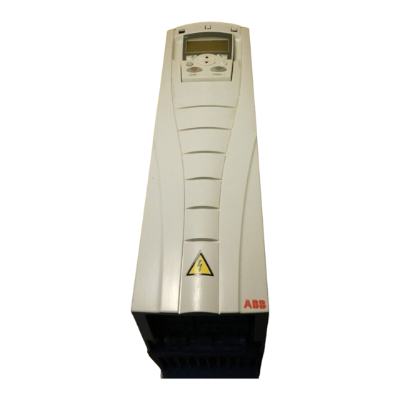
Chapter 2 Installation 2.1 Installation Study these installation instructions carefully before proceeding. Failure to observe the warnings and instructions may cause a malfunction or personal hazard. WARNING: Before you begin read “Safety” on page 1. WARNING: When the ACB530 with Input Disconnect is connected to the line power, the Motor Terminals T1, T2, and T3 are live even if the motor is not running. - Page 8 The following figure shows the front view of the ACB530 Drive with Input Disconnect standard configurations, and identify the major components. 2-2 Installation MN796SUP...
-
Page 9: Installation Flow Chart
2.1.3 Installation Flow Chart The installation of Input Disconnect configurations for ACB530 drives follows the outline below. The steps must be carried out in the order shown. At the right of each step are references to the detailed information needed for the correct installation of the unit. -
Page 10: Preparing For Instllation
2.1.4 Preparing for Installation 2.1.4.1 Lifting the Drive Warning: Handle and ship floor mounted enclosures only in the upright position. These units are not designed to be laid on their backs. 1. Use a pallet truck to move the package/enclosure to the installation site. -
Page 11: Installing The Drive
2.1.4.2 Drive Identification To identify the type of device you are installing, refer to the type code number on the device identification label. • Wall mounting base drives – label attached on the side surface of the heat sink. • Packaged drive with screw cover – label attached to outside surface on the left ide of the enclosure. •... - Page 12 2.1.5.4 Prepare the Mounting Location – R8 The ACB530 should only be mounted where all of the requirements defined in “Preparing for Installation” are met. Frame size R8 has mounting holes inside the enclosure base. See “UL Type/NEMA 1&12, Floor Mount Enclosure Mounting Dimensions”.
-
Page 13: Installing The Wiring
2.1.5.5 Remove Side Panels – R8 UL Type/NEMA 1 & 12 Enclosures Cabinet Door 1. To open the cabinet door, loosen the quarter-turn screws that hold the cabinet door closed. 2. Installation access is easier if these panels are kept off throughout the installation. - Page 14 Power Connection – Standard Drive with Input Disconnect (Floor Mounted) UL Type/NEMA 1 & 12 floor mounted ACB530 Standard Drive with Input Disconnect units are configured for wiring access from the top and include a removable conduit mounting plate. The following figure shows the wiring connection points. Refer to MN796, the ACB530-U1 User’s Manual for control connections to the drive.
-
Page 15: Maintenance
Chapter 3 Maintenance 3.1 Maintenance 3.1.1 Maintenance Intervals If installed in an appropriate environment, the drive requires very little maintenance. This table lists the routine maintenance intervals recommended by Baldor. Maintenance Configuration Interval Instruction Check/replace floor mount Floor mount UL Type / Check every 3 months. - Page 16 3.1.3.1 Floor Mount– UL Type / NEMA 12 Enclosures The enclosure fan is located in the exhaust box on top of the UL Type / NEMA 12 enclosure. 1. Remove the left and right filter frames of the exhaust fan box by lifting them upwards.
-
Page 17: Floor Mount - Ul Type / Nema 12 Filter Material
6. Install the new fan and capacitor with the replacement part for Baldor in the reverse order of the above. Ensure the fan is centered on the velocity stack and rotates freely. 3.1.4 Floor Mount - UL Type / NEMA 12 Filter Material Enclose Type Inlet (door) Outlet (roof) - Page 18 Install the replacement filter. Be sure to tuck the filter into the grove around the entire filter frame. This is very important for proper installation. Reinstall the 3 filter restraining brackets. These will prevent the filter from being pulled out of the filter frame.
- Page 19 1. Remove each filter frame: • Lift up on the filter frame until it slides approximately ¾ inch. • Pull away from the exhaust box to remove. 2. For each filter frame, remove the wire retainers that hold the filters in place: •...
- Page 20 3-6 Maintenance MN796SUP...
-
Page 21: Technical Data
Chapter 4 Technical Data 4.1 Ratings Note: The ratings listed below are exceptions to the ratings listed in MN796, the ACB530-U1 User’s Manual. 4.1.1 Ratings, 480 Volt Drives Valid up to 40°C (104 °F) Type Code Normal Use Heavy-Duty Use Frame Size ACB530-Px-see below -316A-4... -
Page 22: Motor Connections
4.2.2.1 480 Volt, Terminals 480 Volt Power Wiring Data Base Drive Frame Circuit Breaker Ground Lugs Size Type Code UL Type / NEMA1 Motor Terminals UL Type / NEMA1 & 12 & 12 ACB530-PC-316A-4 2 x 500 ACB530-PC-368A-4 ACB530-PC-414A-4 274 in-lbs 2 x 500 MCM 5 Bus Bar 500 in-lbs... -
Page 23: Dimension Reference
4.4 Dimensional Reference The following tables contain dimensional references that identify the dimensional information applying to a given type code. 4.4.1 480V Drive with Disconnect (+B055) Base UL Type / UL Type / Type Code Drive NEMA 1 NEMA 12 Frame Dim. -
Page 24: Ul Ul Type / Nema 1&12, Floor Mount Enclosure Mounting Dimensions
Dimensions: ACB530-PxR UL Type / NEMA 12 UL Type / NEMA 1 UL Type / NEMA 1 Mounting Dimensions Dimensions and Weights mm kg Dimension [inches] [inches] [lbs] Reference Mouting Height Weight Depth Dimension Weight Hardware Drawing PX1-8 Free Standing Ø16 2125 3AUA000021152... -
Page 25: Applicable Standards
4.6 Applicable Standards Drive compliance with the following standards is identified by the standards “marks” on the type code label. Mark Applicable Standards UL 508C and UL Standard for Safety, Power Conversion Equipment, C22.2 No. 14 second edition and CSA Standard for Industrial Control Equipment UL 508A UL Standard for Safety, Industrial Control Panels... - Page 26 4-6 Technical Data MN796SUP...
- Page 27 Baldor Sales Offices UNITED STATES ILLINOIS NEW YORK TEXAS CHICAGO AUBURN DALLAS ARIZONA 340 REMINGTON BLVD. ONE ELLIS DRIVE 2920 114TH STREET SUITE 100 PHOENIX BOLINGBROOK, IL 60440 AUBURN, NY 13021 GRAND PRAIRIE, TX 75050 4211 S 43RD PLACE PHONE: 630-296-1400 PHONE: 315-255-3403 PHONE: 214-634-7271 PHOENIX, AZ 85040...
- Page 28 !796SUP-1114* P.O. Box 2400, Fort Smith, AR 72902-2400 U.S.A., Ph: (1) 479.646.4711, Fax (1) 479.648.5792, International Fax (1) 479.648.5895 Baldor - Dodge 6040 Ponders Court, Greenville, SC 29615-4617 U.S.A., Ph: (1) 864.297.4800, Fax: (1) 864.281.2433 www.baldor.com © Baldor Electric Company All Rights Reserved.
Need help?
Do you have a question about the ACB530 Series and is the answer not in the manual?
Questions and answers