Table of Contents
Advertisement
Advertisement
Table of Contents

Related Manuals for UE Systems ULTRAPROBE 15,000


Summary of Contents for UE Systems ULTRAPROBE 15,000
- Page 1 UE SYSTEMS INC. THE ULTRAPROBE 15,000 MANUAL...
-
Page 2: Table Of Contents
TABLE OF CONTENTS OVERVIEW Introduction Ultraprobe 15,000 Kit COMPONENTS Plug-In Modules Scanning Module Contact Module LRM – Long Range Module RAM/RAS-MT REMOTE MAGNETIC TRANSDUCER Pistol Grip Housing Key Features On/Off/Suspend button Turn Off Suspend SD Card Trigger Switch Touch Screen Display... - Page 3 TFSM - Telescoping Flexible Scanning Module TFCM - Telescoping Stethoscope Module UFMTG-1991 – Multi-directional WTG BCH-WTG – WTG Charger HTS-10 – Holster Set DISPLAY ICONS SETTING UP THE ULTRAPROBE 15,000 Turn on the Ultraprobe 15,000 Home Screen Main Screen (dB) Setup Screen dB/Temp...
- Page 4 Camera Strobe Bluetooth Trigger Switch Quick Change Battery Wrist Strap Headset Jack Recharge Jack Charging Pod USERS INSTRUCTIONS Trisonic- Scanning Module Method of Airborne Detection Headset Rubber Focusing Probe Long Range Module Stethoscope Module Stethoscope Extension Kit RAM-MT Magnetic Transducer Charging The UP15000 Warble Tone Generator Charging The Warble Tone Generator...
-
Page 5: Overview
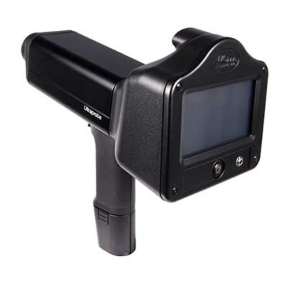
OVERVIEW INTRODUCTION The Ultraprobe 15,000 is a versatile instrument with many features that will make for easy, fast and accurate inspections. As with any new instrument, it is important to review this manual before using the it for inspections. ULTRAPROBE® 15,000 KIT... -
Page 6: Plug-In Modules
COMPONENTS PLUG-IN MODULES TRISONIC SCANNING MODULE. This module is utilized to receive air-borne ultrasound such as the ultrasounds emitted by pressure/vacuum leaks and electrical discharges. There are four prongs at the rear of the module. For placement, align the prongs with the four corresponding jacks in the front end of the pistol housing and plug in. -
Page 7: Lrm - Long Range Module
LRM (LONG RANGE MODULE). A cone shaped scanning module that increases the detection distance above standard scanning modules. The LRM-15 is ideal for high voltage inspection and for locating leaks at great distances. RMT REMOTE MAGNETIC TRANSDUCER. The RMT is a magnetically mountable contact probe with cable. The probe is applied to a test surface and the RAM (Remote Access Module) is plugged into the front end of the Ultraprobe. -
Page 8: Sd Card
Home Screen and touch this icon. A prompt will appear when it is safe to turn the instrument off. Be sure the SD card is inserted in the Ultraprobe 15,000 before NOTE: turning it on. ALWAYS touch the “REMOVE SD CARD” icon before removing the SD card. - Page 9 CAMERA. The camera can be used to capture images of test points or items of interest that can be added into DMS reports. INFRARED THERMOMETER. This non-contact thermometer will measure the temperature of a test point. It can be used in the Temp screen and in the dB/Temp screen.
- Page 10 31 additional inches (78.7 cm) with the Stethoscope Module. BATTERY (2). This Ultraprobe 15,000 uses a lithium ion battery. A full charge will take about 4 hours; however, it is possible to charge the unit at any time for short intervals or for a longer period.
-
Page 11: Optional Accessories
UE-BATTERY CHARGER POD. This is a Battery Recharge Pod docking station for charging Ultraprobe Batteries (Lithium Ion only). This pod will charge the standard batteries that come with the Ultraprobe 15,000 while removed from the metered pistol housing. OPTIONAL ACCESSORIES CFM-15. -
Page 12: Tfcm - Telescoping Stethoscope Module
TFCM: Telescoping Stethoscope (Contact) Module. A contact probe for structure borne inspection that can be extended for hard to reach areas. UFMTG-1991. The UFMTG 1991 is a multi-directional warble tone generator. It has a high-power output with a circular transmission pattern of 360 degrees. BCH-WTG. -
Page 13: Display Icons
DISPLAY ICONS View uploaded route The main default screen Main Screen displays dB Adjust Emissivity Display for dB and View a specific historical temperature record Turns off/on Temperature sensing Input additional test data to record Spectral Analysis screen & function Store test data Set up instrument functions Exit screen... -
Page 14: Setting Up The Ultraprobe 15,000
SETTING UP THE ULTRAPROBE 15,000 TO TURN ON THE ULTRAPROBE 15,000 Press and then release the ON/OFF button as shown. Be sure the SD card is inserted in the Ultraprobe NOTE: 15,000 before turning it on. ALWAYS touch the “REMOVE SD CARD”... -
Page 15: Setup Mode
SET UP MODES & FEATURES Before using the instrument, become familiar with the various features and modes of operation. The user can customize the instrument to meet plant specific inspection demands. This is accomplished in the SETUP Mode. To enter the set up mode: Turn the instrument on. - Page 16 The Automatic setting is used after the initial baseline data has been uploaded to the Ultraprobe 15,000. In the Automatic setting, the instrument will move sequentially from one test point to the next, and set itself for the original baseline setup, which will include the Frequency and Sensitivity for that point.
-
Page 17: Info
Upgrade Progm (Program): The options are “Yes” or “No”. When there is an upgrade to the Ultraprobe 15,000 it may be downloaded off the web onto the SD card. Insert the SD card with the upgrade and use Upgrade Program. -
Page 18: Applications
Upgrade Lang (Language): The options are “Yes” or “No”. Contact UE Systems for assistance. APPLICATIONS Each application has unique data. When an application is selected the instrument will automatically set up specific fields that are unique to that application. -
Page 19: Using Screens
USING THE SCREENS To use any of the screens: Turn on the Ultraprobe by pressing the ON button When the Home screen opens, select an Icon To use an operational screen such as “Main”, “dB/Temp”, “Temp”, or Valve. Pull the trigger in and begin the inspection. If no or very little ultrasound is present, or if the sensitivity value is too high for the test area, the dB will not show on the screen. -
Page 20: Using Db/Temp Screen
Viewing changes in Decibel Levels: To view decibel levels the Ultraprobe must be in the active scan mode. Pull the trigger in to activate the active scan mode. To freeze the data for storage, while pointing or touching the test point in the active mode, release the trigger. -
Page 21: Using Valve/Steam Screen
To test for a temperature the instrument must be in the active scan mode: d. Pull the trigger to activate the Active Scan Mode. e. To freeze the data for storage, while pointing or touching the test point in the active mode, release the trigger. -
Page 22: Using Spectra (Fft) Screens
e. When done, touch the bottom of the screen and locate the save icon, touch save, when prompted, touch yes to save. SPECTRALYZER The onboard Spectralyzer displays sound events in either an FFT screen, a Time Series Screen or Both screens at the same time. There are 6 buttons to use at the bottom of the displayed screen: START/STOP, PLAY, CAPTURE, REC, SETTINGS, AND EXIT. -
Page 23: Storing A Record
Control: On the bottom-right of the LEVELS screen is the Control box. Labeled “Control” Touch to enter. The settings are: Screen views: Select FFT screen or Time Series Screen or view both on the same screen by selecting both. Black /White plot: The default screen colors are blue and yellow, this can be changed to black and white. -
Page 24: View Record
e. Use the UP/DOWN arrows to enter the desired data. f. These input data fields are set (and may be changed) in Ultratrend DMS. VIEW RECORD A record can be viewed in an operational screen. The record number can be changed to display the record desired. a. - Page 25 CAMERA To take a photo of a test point, touch the Camera icon. The Camera screen will show: a. Flash: On/Off: The flash is on by default. To turn the flash “Off”, touch the flash icon. A red line will appear through the icon indicating it is off.
-
Page 26: Trigger Switch
d. To save the RPM, touch the Save icon. The RPM will be transferred to the DMS software later. e. Touch the Exit icon to exit. The RPM data will be stored in the “RPM” field under the “Record Information” tab NOTE: once the data is transferred from the UP15000 into the DMS software. - Page 27 Keep a backup battery fully charged using the Charging Pod. This is a battery recharge docking station for charging Ultraprobe Batteries (Lithium Ion). This pod will charge the standard batteries that come with the Ultraprobe 15,000 while removed from the metered pistol housing.
-
Page 28: Headset
USERS INSTRUCTIONS TRISONIC SCANNING MODULE This module plugs into the front end of the instrument. Align the pins located at the rear of the module with the four jacks in the front end of the Metered Pistol Housing (MPH) and plug in. For general use position the frequency selection to 40 kHz. -
Page 29: Stethoscope Extension Kit
LONG RANGE MODULE (LRM) This module plugs into the front end of the instrument. Align the pins located at the rear of the module with the four jacks in the front end of the Metered Pistol Housing (MPH) and plug in. For general use position the frequency selection to 40 kHz. - Page 30 Charge time is approximately 4 hours. WARNING: Use the supplied UE Systems recharger (BCH-10L) only. Use of unauthorized rechargers will void the warranty and may degrade or damage the battery. WARBLE TONE GENERATOR / SENSITIVITY VALIDATION UNIT (UE-WTG-1) The Tone Generator has two functions.
- Page 31 A message in the Display Panel will read “RECHARGE BATTERY”, and the instrument will go into a “sleep” mode. The instrument will automatically store all records onto the SD card at shutdown. After the battery is replaced with a freshly charged battery, turn the Ultraprobe 15,000 back on to continue testing.
-
Page 32: Battery
ULTRAPROBE 15,000 SPECIFICATIONS CONSTRUCTION Hand-held pistol type made with coated aluminum and ABS plastic. CIRCUITRY Solid State Analog and SMD Digital Circuitry with temperature compensation and true RMS conversion. 20 KHz to 100 KHz (tunable in 1 KHz increments) FREQUENCY... - Page 33 Ultraprobe 15,000 Kit: Meets and exceeds ASTM E1002-2005 requirements for Leak Detection. Covered by one or more of the following patents: 0151115; 0303776; 0315199; 1206586; 1297576; 1881263; 2562758; 2689339; 4416145; 4823600; 5955670; 6122966; 6339961; 6341518; 6415645; 6655214; 6707762; 6804992 © 2010 UE Systems, Inc. Made in USA. UE 15 – 0110 UE Systems is committed to continual product improvement;...
- Page 34 INSTRUCTIONS FOR SETTING COMBINATION ON CARRYING CASE The combination is factory set at --0--0--0 SETTING YOUR PERSONAL COMBINATION Open the case. Looking at the back of the lock inside the case you will see a change lever. Move this change lever to the middle of the lock in a way that allows it to hook behind the change notch (drawing 1).
- Page 35 APPENDEX A - SENSITIVITY CALIBRATION ULTRASONIC TONE GENERATOR METHOD ULTRAPROBE 15000 It is advisable to check the sensitivity of the instrument before proceeding with any inspection. To assure reliability keep a record of all the sensitivity validation tests and be sure to keep the Warble Tone Generator charged.
- Page 36 9. Note the level (L or H) in the TG box of the Sensitivity Validation chart. 10. Turn the Ultraprobe 15,000 on its’ side so that it will rest flat on the test table with the handle facing the user and the Scanning Module facing the Tone Generator.
- Page 37 Note the level (H or L) in the TG box of the Sensitivity Validation chart. With the handle facing the user, align the tip of the contact probe with the recharge jack and allow the probe to rest on the jack. DO NOT PRESS DOWN! (NOTE: NEVER USE THE ALUMINUM EXTENSION PROBE RODS THEY WILL SHORT OUT THE BATTERY OF THE WTG).
- Page 38 Need further support? Want information regarding products or training? CONTACT: UE Systems, Inc. 14 Hayes Street, Elmsford, NY 10523 USA 914-592-1220 | info@uesystems.com | www.uesystems.com...
Need help?
Do you have a question about the ULTRAPROBE 15,000 and is the answer not in the manual?
Questions and answers