Table of Contents
Advertisement
Quick Links
Advertisement
Table of Contents

Related Manuals for PSA Products Panacom PANAIPDS


Summary of Contents for PSA Products Panacom PANAIPDS
- Page 1 TCP/IP DOOR PANEL QUICK SETUP GUIDE MODEL NO: PANAIPDS...
-
Page 2: Table Of Contents
6. Door Panel Quick Setup If the product emits a peculiar noise, odour or smoke, immediately disconnect the power, and then contact PSA Products. Main Screen Do not insert the power plug into a 240VAC mains socket with a wet hand... -
Page 3: Technical Specifications
1. TECHNICAL SPECIFICATIONS 2. PACKING CONTENTS • 3.5” TFT LCD screen. Resolution: 320*240 pixels • White LED for night vision • Wide angle horizontal 128° • Operating System: Linux System • Network Connection: POE • Operating Voltage: 18V (POE) • : -40 ~ 55ºC Operation Temperature •... -
Page 4: Name And Functions Of Each Part
3. NAME AND FUNCTIONS OF EACH PART 4. CONNECTION DIAGRAM 3.1 FRONT AND REAR PART 4.1 SYSTEM LAYOUT Remark: • The distance between devices (indoor monitor, door panel, network switch, guard unit, and POE Switch) and PoE Switch is limited to 70 meters. •... -
Page 5: Wiring Diagram
4. CONNECTION DIAGRAM (CONTINUED) 4.2 WIRING DIAGRAM 4.3 ELECTRIC LOCK CONNECTION Attention: Note: • The panel uses its own special POE power supply system. (Part No: PANAIPPOE) 1. Ensure the external power supply is selected to suit the door lock. The door lock power Do not connect the Panel to a standard POE switch!!! consumption must not exceed 30VDC @ 2A. -
Page 6: Installation
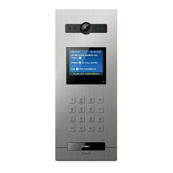
5. INSTALLATION 6. DOOR PANEL QUICK SETUP CAMERA INSTALLATION LOCATION 6.1 MAIN SCREEN Standard installation height of door panel puts the lens about 1550mm above the floor. When in standby mode, and if movement is detected, the screen will turn on. A sample Hence, the centre of the camera should be about 1540mm above ground level. -
Page 7: Set Encoder And Device Id
6. DOOR PANEL QUICK SETUP (CONTINUED) 6.3 SET ENCODER AND DEVICE ID 6.4 PROGRAM ACCESS CARDS Before the access cards are programmed, all the monitors must first be configured into the system. to navigate To enter Setup page Select Device Information + Press: Press to select 5 Digit encoding. -
Page 8: Copy Cards To Another Door Panel
6. DOOR PANEL QUICK SETUP 7. DOOR PANEL MANUAL (CONTINUED) 6.5 COPY CARDS TO ANOTHER DOOR PANEL To download Door Station manual, go to: www.psaproducts.com.au Select [Copy To] + to enter door panel list page; Select the Door Panel you want to copy to, and then press to confirm. - Page 9 17 Millicent Street, Burwood, VIC 3125 Australia Tel: 1300 PSA PRODUCTS (1300 772 776) Fax: (03) 9888 9993 psaproducts.com.au enquiry@psaproducts.com.au...
Need help?
Do you have a question about the Panacom PANAIPDS and is the answer not in the manual?
Questions and answers