Table of Contents
Advertisement
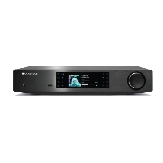
Issue date: April 2015
Service Manual
CXN
Specifications
Technical specifications
DAC
Dual Wolfson WM8740 24-bit DACs
Digital filter
2nd Generation ATF2 up-sampling to 24-bit/384KHz
Analogue filter
2-Pole Dual Differential Bessel
USB Type B conforms to USB Audio profile 1.0 or 2.0 (user selectable)
USB Audio Input
and DSD via USB
Digital audio inputs
S/PDIF Coaxial and TOSLINK Optical
UPnP, Local USB media, USB audio 1.0 and 2.0, S/PDIF Toslink and
Compatibility
Coaxial, Airplay, BT100 Bluetooth receiver (not supplied), Internet radio,
Spotify Connect
Audio formats
ALAC, WAV, FLAC, AIFF, WMA, MP3, AAC, HE AAC, AAC+, OGG Vorbis
Max power consumption
30W
Standby power consumption
0.5W
maximum including sockets and controls
Dimensions (H x W x D)
85 x 430 x 305mm (3.4 x 16.9 x 12.2")
Weight
3.5Kg (7.7Lbs)
Advertisement
Table of Contents

Related Manuals for Cambridge Audio CXN


Summary of Contents for Cambridge Audio CXN
- Page 1 Issue date: April 2015 Service Manual Specifications Technical specifications Dual Wolfson WM8740 24-bit DACs Digital filter 2nd Generation ATF2 up-sampling to 24-bit/384KHz Analogue filter 2-Pole Dual Differential Bessel USB Type B conforms to USB Audio profile 1.0 or 2.0 (user selectable) USB Audio Input and DSD via USB Digital audio inputs...
-
Page 2: Table Of Contents
All trademarks and registered trademarks are the property of their respective owners. © Copyright Cambridge Audio Ltd 2015. Cambridge Audio and the Cambridge Audio logo are trademarks of Cambridge Audio. -
Page 3: Exploded Diagram
Exploded Diagram exploded view ref Description Service Part Number remote control (CXN, CXC, CXA) PZ804 Edimax Wi Fi dongle PZ716 UK IEC TO PIERCE EPE PLEASE NOTE ALL POLYBAGS ARE NOT... -
Page 4: Front Panel Exploded Diagram
4.3 inch TFT Display PZ786 Complete front panel including metalwork in black PKA013 Complete front panel including metalwork in silver PKA014 Knob in black (order with insert PKA042) PZ840 Knob in silver (order with insert PKA042) PZ841 Knob insert CXN/CXA60/80 PKA042... -
Page 5: Product Assy Exploded Diagram
Product Assy Exploded Diagram exploded diagram ref Description Service Part Number Control Bus PCB PKA011 Audio PCB (main board) PKA010 SMPS PCB assy (same as SM6 v2) PF505 Top cover black PKA015 Top cover silver PKA016. -
Page 6: Cxn Block Diagram - Master
Service Manual CXN Block Diagram - Master ... -
Page 7: Cxn Block Diagram - Signal Path
CXN Block Diagram - Signal Path... -
Page 8: Cxn Block Diagram - Control Lines
Service Manual CXN Block Diagram - Control Lines ... -
Page 9: Cxn Block Diagram - Clock Signals
CXN Block Diagram - Clock Signals ... -
Page 10: Cxn Front Panel Pcb Schematic
Service Manual CXN Front Panel PCB Schematic ... -
Page 11: Front Panel Top
Front Panel Top... -
Page 12: Front Panel Bottom
Service Manual Front Panel Bottom... -
Page 13: Front Panel Pcb Bom
Front panel PCB BOM Value Description/Type Component Ident ManPN Tolerance PackageInfo Notes Service Part 13.3k 0603 Thick Film 0603 R3, R6-R8, R11, R16, R24, NO FIT R27-R30, R35, R40 0603 Thick Film 50mR 0603 NO FIT R10, R13, R34, R113 0805 Thick Film 0805 0603 Thick Film... -
Page 14: Audio Pcb Schematic Power Supply
Service Manual Audio PCB Schematic Power Supply ... -
Page 15: Audio Pcb Schematic Usb Circuit Powe Supply
Audio PCB Schematic USB Circuit Powe Supply ... -
Page 16: Audio Pcb Schematic Spdif I/O Reply
Service Manual Audio PCB Schematic SPDIF I/O Reply ... -
Page 17: Audio Pcb Schematic Usb Streaming Phy
Audio PCB Schematic USB Streaming PHY ... -
Page 18: Audio Pcb Schematic Dsp And Dir
Service Manual Audio PCB Schematic DSP and DIR ... -
Page 19: Audio Pcb Schematic Masterclocks
Audio PCB Schematic Masterclocks ... -
Page 20: Audio Pcb Schematic Dsp Decoupling & Sram
Service Manual Audio PCB Schematic DSP Decoupling & SRAM... -
Page 21: Audio Pcb Schematic Wm8740/1/2 Dacs
Audio PCB Schematic WM8740/1/2 DACs ... -
Page 22: Audio Pcb Schematic Mcu And Flash
Service Manual Audio PCB Schematic MCU and Flash ... -
Page 23: Audio Pcb Schematic Ethernet And Usb Hub
Audio PCB Schematic Ethernet and USB HUB ... -
Page 24: Audio Pcb Schematic Zander
Service Manual Audio PCB Schematic ZANDER ... -
Page 25: Audio Pcb Schematic Apple Test Points And Emc Points
Audio PCB Schematic Apple Test Points and EMC Points ... -
Page 26: Audio Pcb Schematic Analogue Stage
Service Manual Audio PCB Schematic ANALOGUE STAGE ... -
Page 27: Audio Pcb Top
Audio PCB Top ... -
Page 28: Audio Pcb Bottom
Service Manual Audio PCB Bottom... -
Page 29: Audio Pcb Bom
Audio PCB BOM Value Description/Type Component Ident ManPN Tolerance PackageInfo Notes Service Part RESISTORS R17, R19-R20, R38, R40, R50, R85, R108, R114, R122-R124, R241, R246-R248, R272, R291, R297, R327, 0603 Thick Film 50mR 0603 R355, R362, R368, R383, R387-R389, R391-R392, R394, R396, R408, R435, R715, R836, R942 R32, R51, R141, R154, R271, R277, R414, R804, NO FIT... - Page 30 Service Manual 0204 Melf R194-R197, R218-R221 0204 0603 Thick Film R6, R320 0603 0204 Melf R180-R181, R188-R189, R204-R205, R212-R213 0204 0603 Thick Film R321 0603 R182-R183, R190-R191, R198-R199, R206-R207, 0204 Melf 0204 R214-R215, R222-R223 0603 Thick Film 0603 0603 Thick Film R23, R35 0603 0204 Melf...
- Page 31 C33, C70-C71, C74-C80, C88, C107-C110, C112, C114, C122-C124, C467, C469-C472, C474-C480, C553-C554, 100pF 50V NP0 0402 0402 C557-C558, C569-C576, C585-C593, C596, C599, C620-C621, C625-C626 100pF 50V 0805 NP0 Ceramic C406 0805 5mm Pitch 150pF 100V Polypropylene C277, C282, C288-C289, C312-C313, C318-C319 FKP2D001501D00J 560pF 50V NP0 0805...
- Page 32 Service Manual 1N4148 D1, D403-D406 1N4148 SOD80 1A 30V Schottky Rectifier D2, D407, D412-D413 STPS1L30U DO214 NO FIT D3, D5-D8 NO FIT NO FIT D9-D10 NO FIT Dual Signal Diode 75V 0.215A D31-D34 BAW56 SOT23 200V 1.0A SM Rectifier D400, D408-D410 RS1D DO214 NO FIT...
- Page 33 NO FIT Programmable Si5351A-B Si5351A-B-GT 10-MSOP Clock Generator NO FIT WM8740 24bit/192kHz DAC U54, U58 WM8740SEDS SSOP28 PY585 NE5532 Dual Audio Op Amp U55-U56, U59-U60 NE5532D SOIC08 PY1162 OP275 Dual Audio Op Amp U57, U61 OP275GSZ SOIC08 PF780 Through 25Mbps TOSLink Receiver U401 DLR2111...
-
Page 34: Bus Pcb Schematic
Service Manual BUS PCB Schematic ... -
Page 35: Control Bus Top
Control BUS Top... -
Page 36: Control Bus Bottom
Service Manual Control BUS Bottom... -
Page 37: Control Bus Bom
Control BUS BOM Value Description/Type Component Ident ManPN Tolerance PackageInfo Notes Service Part RESISTORS 1206 Thick Film R1-R4 50mR 1206 0805 Thick Film 0805 0603 Thick Film 0603 100R 0805 Thick Film 0805 220R 0805 Thick Film R95-R96 0805 0603 Thick Film R39-R40 0603 0603 Thick Film... -
Page 38: Front Daughter Pcb Schematic
Service Manual Front DAUGHTER PCB Schematic ... -
Page 39: Front Panel Daughter Top Pcb
Front Panel DAUGHTER Top PCB... -
Page 40: Front Panel Daughter Bottom Pcb
Service Manual Front Panel DAUGHTER Bottom PCB... -
Page 41: Front Panel Daughter Pcb Bom
Front Panel DAUGHTER PCB BOM Value Description/Type Component Ident ManPN Tolerance PackageInfo Notes Service Part RESISTORS NO FIT R53-R54 1206 Thick Film 1206 CAPACITORS 10pF 50V NP0 CER 0603 C611-C612 0603 100nF 50V C3, C9 0603 10uF 25V 1206 CONNECTORS USB Type A Black Insert Socket 18004-X11X102N... -
Page 42: Encoder Pcb Schematic
Service Manual ENCODER PCB Schematic... -
Page 43: Encoder Top & Bottom
ENCODER Top & Bottom... -
Page 44: Encoder Pcb Bom
Service Manual ENCODER PCB BOM Value Description/Type Component Ident ManPN Tolerance PackageInfo Notes Service Part RESISTORS NO FIT R88, R101, R103, R106-R107 NO FIT R100 0603 Thick Film R89, R139 0603 0603 Thick Film R81, R84 0603 100R 0603 Thick Film R66, R85 0603 0603 Thick Film... -
Page 45: Smps Schematic Pcb
SMPS Schematic PCB 2M2/1/4W (CCR) EC13 47UF/450V 10K 0.25% 150K 1% 4700PF(NPO) 1000U/10V 120PF(NPO) 1000U/10V EC10 1000U/10V EC11 100U/10V... -
Page 46: Smps Pcb Layout
Service Manual SMPS PCB LAYOUT... -
Page 47: Smps Pcb Bom
SMPS PCB BOM Used Part Type Designator Jumper CF Resistor ±5% 1/8W CF Resistor ±5% 1/8W CF Resistor ±5% 1/8W 560R CF Resistor ±5% 1/8W CF Resistor ±5% 1/8W 2.2K CF Resistor ±5% 1/8W R7 R9 R11 R26 R28 CF Resistor ±5% 1/8W R10 R29 R31 R32 R34 CF Resistor ±5% 1/8W R27 R30 R33...
Need help?
Do you have a question about the CXN and is the answer not in the manual?
Questions and answers