
Related Manuals for tams elektronik GBM-1


Summary of Contents for tams elektronik GBM-1
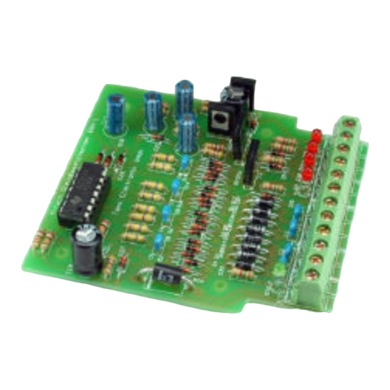
- Page 1 GBM-1 Gleisbesetztmelder Track Busy Indicator Indicateur d’occupation Railbezetmelder Anleitung Manual Mode d´emploi Handleiding Art.-Nr. 21-01-026 / 22-01-026...
- Page 2 © 09/2006 Tams Elektronik GmbH Alle Rechte, insbesondere das Recht der Vervielfältigung und Verbreitung sowie der Übersetzung vorbehalten. Vervielfältigungen und Reproduktionen jeglicher Form bedürfen schriftlichen Genehmigung durch die Tams Elektronik GmbH. Deutsch Technische Änderungen vorbehalten. © 09/2006 Tams Elektronik GmbH English All rights reserved.
-
Page 3: Table Of Contents
English GBM-1 Table of contents How to use this manual Intended use Safety instructions EMC declaration Operation overview Technical specifications Checking the package contents Required tools and materials Safe and correct soldering Assembling the kit Performing a visual check Performing a functional test... -
Page 4: How To Use This Manual
GBM-1 English How to use this manual If you have no specialist technical training, this manual gives step-by- step instructions for safe and correct assembly of the kit and fitting of the ready-built module, and operation. Before you start, we advise you to read the whole manual, particularly the chapter on safety instructions and the FAQ chapter. -
Page 5: Safety Instructions
English GBM-1 Safety instructions Mechanical hazards Cut wires can have sharp ends and can cause serious injuries. Watch out for sharp edges when you pick up the PCB. Visibly damaged parts can cause unpredictable danger. Do not use damaged parts: recycle and replace them with new ones. - Page 6 GBM-1 English Fire risk Touching flammable material with a hot soldering iron can cause fire, which can result in injury or death through burns or suffocation. Connect your soldering iron or soldering station only when actually needed. Always keep the soldering iron away from inflammable materials.
-
Page 7: Emc Declaration
English GBM-1 EMC declaration This product is developed in accordance with the European standards EN 55014 and EN 50082-1, tested corresponding to the EC - directive 89/336/EWG (EMVG of 09/11/1992, electromagnetic tolerance) and meets legal requirements. To guarantee the electromagnetic tolerance you must take the following precautions: §... -
Page 8: Technical Specifications
GBM-1 English Technical specifications Supply voltage 12-18 Volt a.c. voltage Current consumption (without connected loads) approx. 15 mA Max. current per output 250 mA Protected to IP 00 Ambient temperature in use 0 - + 60 °C Ambient temperature in storage -10 - + 80 °C... -
Page 9: Safe And Correct Soldering
English GBM-1 § a pair of tweezers and long nose pliers (not necessary for the ready-built module), § a lamp or bulb for the functional test. Safe and correct soldering Caution: Incorrect soldering can cause dangers through fires and heat. Avoid these dangers by reading and following the directions given in the chapter Safety instructions. -
Page 10: Assembling The Kit
GBM-1 English § To make a good soldering joint you must use a clean and unoxidised soldering tip. Clean the soldering tip with a damp piece of cloth, a damp sponge or a piece of silicon cloth. § Cut the wires after soldering directly above the PCB solder side with a side cutter. - Page 11 English GBM-1 Capacitors Among other things capacitors are used for filtering interference voltages or as frequency determining parts. Ceramic capacitors are not polarized, for that reason their mounting orientation is of no importance. Normally they are marked with a three-digit number which indicates the value coded.
- Page 12 GBM-1 English Light emitting diodes (LEDs) When operated in the forward direction the LEDs light. They are available in several different versions (differing in colour, size, form, luminosity, maximum current, voltage limits). The longer lead of wired LEDs is always the anode (positive pole).
-
Page 13: Performing A Visual Check
English GBM-1 Terminal strips Terminal strips are solder-in screw-type terminals. They provide a solder-free and safe connection of the cables to the circuit, which can still be seperated any time. When several terminal strips have to be mounted side by side, they have to be put together before mounting. -
Page 14: Performing A Functional Test
GBM-1 English Caution: Do not power up the module yet. Check all nuts, pins and connections as well as the mechanical connections for correct assembly. The following points are inapplicable if you have purchased a ready- built module. § Remove all loose parts, wire ends or drops of solder from the PCB. -
Page 15: Connecting The Track Busy Indicator
English GBM-1 Caution: If a component gets too hot, disconnect the booster and transformer from the mains immediately. Possible short circuit! Check the assembly again. After performing a successful function test, disconnect the track busy indicator from the voltage supply and continue with the connection of the module. -
Page 16: Faq
GBM-1 English § Parts are getting too hot and/or start to smoke. Disconnect the system from the mains immediately! Possible cause: one or more components are soldered incorrectly. à Perform a visual check. § The lamps connected to the module do not light. -
Page 17: Conditional Warranty
English GBM-1 Conditions of warranty This product is guaranteed for two years. The warranty includes the correction of faults which can be proved to be due to material failure or factory flaw. As we have no control over the correct and proper assembly and mounting we can only guarantee the quality of the components and the completeness of kits. - Page 18 GBM-1 Stückliste - Parts list Nomenclature - Stuklijst 470 Ω Widerstände Resistors R4, R7, R10, R13, 10 kΩ Résistances R14, R16, R18, R20 Weerstanden R2, R3, R5, R6, R8, 470 kΩ R9, R11, R12 R15, R17, R19, R21 47 kΩ...
- Page 19 GBM-1 Fig. 1: Bestückungsplan - PCB layout Plan d´implantation - Printplan Seite - Page - Page - Pagina I.2...
-
Page 20: Circuit Diagram (Fig. 2)
GBM-1 GBM-1 Fig. 2: Schaltplan Circuit Diagram Schéma de principe Schakelplan Seite - Page - Page - Pagina II Seite - Page - Page - Pagina II... - Page 21 GBM-1 GBM-1 Fig. 3: Anschlußplan - Connection Diagram - Plan de connexion - Aansluitplan Seite - Page - Page - Pagina III Seite - Page - Page – Pagina III...
- Page 22 Actuele informatie en tips: http://www.tams-online.de Garantie und Service: Warranty and service: Garantie et service: Garantie en service: Tams Elektronik GmbH Rupsteinstraße 10 D-30625 Hannover fon: +49 (0)511 / 55 60 60 fax: +49 (0)511 / 55 61 61 e-mail: modellbahn@tams-online.de...
Need help?
Do you have a question about the GBM-1 and is the answer not in the manual?
Questions and answers