Table of Contents
Advertisement
Advertisement
Table of Contents

Related Manuals for eove EO-150


Summary of Contents for eove EO-150
- Page 1 EO-150 Ventilator User Guide Applies from S/N EO1X00120001S 100-23 rev DA_01/2020...
-
Page 3: Table Of Contents
Ventilation module and docking station references................. 12 Menu Bar / Keyboard ........................13 Symbols Table ........................... 13 Chapter 2 – Operating Instructions for the EO-150 ventilator ............. 16 Set Up Test ............................16 Additional tests for alarms from ISO 80601-2-72: ................17 Turning on the device ........................ - Page 4 Prepare the battery for long-term storage ..................48 Connecting to an external DC power source ..................48 EO-150 Car lighter DC cable (Ref EO-CARCBL) - Instructions for use ..........49 Connecting two power sources using the Y cable (EO-CPLPACK or EO-CPLPACKBOX): ....50 Mounting EO150 on trolley (KC072283) ...................
- Page 5 Servicing ............................63 Maintenance Timetable ........................63 Chapter 6 - Device information ......................64 Technical specifications ........................64 Physical Specifications ........................64 Ventilation Specifications ......................... 64 Accuracy of ventilation settings ......................71 Measurements uncertainties ......................71 Monitored Parameter Specifications ....................72 Accuracy of monitoring data ......................
-
Page 6: Introduction
The EO-150 ventilator device provides continuous or intermittent ventilation support for pediatric and adult patients weighing at least 3.5kg (8lbs) who require mechanical ventilation. The EO-150 device is intended to be used in home, institution, hospital and portable environments for both invasive and non-invasive ventilation. -
Page 7: Contraindications
The EO-150 ventilator is not intended for use with flammable anesthetics and neither for use in conjunction with flammable agents. Contraindications Severe hypotension particularly with intravascular volume depletion Pneumothorax or pneumomediastinum After brain surgery or cranial trauma ... -
Page 8: General Warnings And Cautions
EO-150 ventilator in direct contact with the patient for extended periods of time. The EO-150 should be kept out of reach of children and domestic animals to ensure their safety and the safety of the patient and to avoid damage to the ventilator and the accessories. - Page 9 The EO-150 ventilator is not intended for use as an emergency transport ventilator. Do not expose the EO-150 ventilator to excessive force, do not shake or drop. If the ventilator or its power supply are dropped or mishandled, immediately discontinue use and contact your EOVE representative.
-
Page 10: Chapter 1 - Description Of The Eo-150 Ventilator
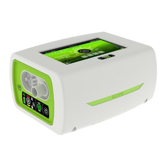
Chapter 1 – Description of the EO-150 ventilator Front Panel 1. Display screen 4. EO device housing unit 2. Ventilation module 5. Inspiratory / Circuit Port 3. Proximal pressure, valve, and proximal flow connectors 6. Menu bar / keyboard... -
Page 11: Rear Panel
Rear Panel 1. Air inlet and hypoallergenic filter 5. USB-1 port (data retrieval) 2. DC Power connector 6. O input 3. Docking station Power Button 7. FiO / SpO connector 4. USB-2 port (maintenance only) 8. Remote Alarm connector... -
Page 12: Rear View Of Ventilator Without Housing
1. USB port (Do not use - limited to maintenance operations as described in the maintenance manual) 2. DC Car charger connection 3. Connection to outer housing Ventilation module and docking station references EO-150 Complete ventilator: EO-150VNT EO-1X0 Docking station reference: EO-DCK1SLT EO150 Ventilator module reference: EO-VM150... -
Page 13: Menu Bar / Keyboard
Menu Bar / Keyboard 1. Power source indicator 6. ON / OFF switch 2. High priority alarm indicator 7. Physiological alarm indicator 3. Technical alarm indicator 8. Medium priority alarm indicator 4. Circuit alarm indicator 9. Alarm reset 5. Ventilation start / stop 10. - Page 14 Maintenance menu Clinical Mode locked Clinical menu Battery power indicator Leak circuit Proximal free configuration Pediatric Patient Waveform selection (normal / loop) Waveform pause Single branch patient circuit with proximal flow Inspiration trigger (I) / Exhalation trigger (E) activation symbols Power off button Help button Active alarm (change of color according to the...
- Page 15 Date of manufacture This side up Manufacturer Complies with European legal requirements High and low temperature limitations for Serial number transport and storage Should not be disposed of in household waste Product reference number Keep dry Recyclable Danger of fire if damaged Copyright Fragile.
-
Page 16: Chapter 2 - Operating Instructions For The Eo-150 Ventilator
If alarms do not sound during the Set Up test, do not use the ventilator. CAUTION Contact your healthcare provider or EOVE for assistance if any of the checks in the set up test fail. If the EO-150 has been returned after servicing, ensure it is clearly labelled as disinfected before starting the set-up test or installing. -
Page 17: Additional Tests For Alarms From Iso 80601-2-72
WARNING Some circuit and accessories configurations (mainly in leak pediatric configuration) with high resistive pressure in the circuit could lead to ineffective "Disconnection alarm". For ventilator dependent patient, "Disconnection alarm" must be tested after any calibration, setting changes or circuit configuration change. In case the disconnection alarm detection is not efficient, it is mandatory to set a VTI Min alarm (leak configurations) or a VTI Max alarm (valve configurations) as a backup for disconnection events covering. -
Page 18: Turning On The Device
3. The ventilator turns OFF and the touch interface turns to a deep-sleep mode. WARNING The EO-150 ventilator cannot be powered off during ventilation From the module - Secondary proceedings 1. Press and hold until the ALARM key flashes. -
Page 19: Using Stand-By Mode
Using Stand-by mode Using Stand-by mode is recommended for an economical use of the battery of EO-150 ventilator, especially in mobile usage. Stand-by mode will reduce luminosity of the screen. That will preserve battery and keep system ready to wake up immediately when needed. -
Page 20: Turning On And Off The Docking Station
Turning on and off the docking station If the module is inserted in the docking station, it will power up and power down automatically following the ventilation module status. During a storage period or a long period of non-use, the docking station should be switched off. To switch on and off the docking station and the touch screen, press the docking station Power button for a few seconds. - Page 21 1. Patient triggered breath indicators 10. Time: Indicates the time on 24hr clock. This (Inspiration / Expiration) can be set up and changed from the Patient 2. Patient mode indicator: Indicates whether Preferences Menu. patient is adult or pediatric. The indicator 11.
-
Page 22: Navigating The Patient Screen And Menu
Navigating the Patient Screen and Menu From this screen the patient can change preferences and calibrate the ventilator. Calibration should be performed at every circuit configuration change and is explained in Chapter 4 of this manual. From the Home Screen, choose to access the Preferences, Calibration, Event Logs, Export data and Monitoring menus. -
Page 23: Navigating The Monitoring Menu
Navigating the Monitoring Menu From this screen the patient or caregiver can access the monitoring menu. This menu is the same as the monitoring menu that can be found in the Clinical menu. Active alarm list To access the list of active alarms for the ventilator, from the Home Screen, touch active alarm list. -
Page 24: Accessing And Using The Clinical Menu
See Chapter 4 for more detailed information on alarms and how to respond to them. Accessing and using the Clinical Menu Do not access clinical mode (unlocked mode ) unless directed by a physician. NOTE: To access the Clinical Menu 1. -
Page 25: Presets
Presets The EO-Series ventilator can store up to four different ventilation presets. Presets can be configured by your clinician to provide personalized alternative treatment options. These preset configurations allow for different treatments according to the time of day or the activity being undertaken by the patient. - Page 26 Changing preset mode 1. Current preset / Activated preset 2. Presets saved and not activated 3. Presets not saved To change the preset, click on the activable preset you want to switch on. Click on the Information icon to display the parameters of the activable preset.
-
Page 27: Circuit / Patient Configuration Menu
Circuit / Patient Configuration Menu NOTE: The Clinician Screen can only be accessed when the Clinical menu is unlocked. This should only be unlocked by a doctor or health care provider or at their request. Access the Patient/ Circuit configuration menu by choosing the “CONFIG” tab From this screen, you can change the settings shown below and perform a calibration. -
Page 28: Other Screens
Scroll down to choose the required mode. Modes with background in grey are not accessible. Other screens Events Log Screen This screen shows all alarms, setting changes, configuration changes and any power on/off events. More than 10000 events can be saved and consulted. The events are displayed by date. - Page 29 Monitorings Screen This screen shows patient physiological data. Wave Forms Screen 1. Flow in red 3.Curve selection: Pressure, flow 2.Pressure in blue 4.Play / Pause waveforms This screen reports the patient data and is updated with every breath. The time scale adapts to the patient’s respiration rate every minute.
- Page 30 This screen shows the Patient Monitoring values which correspond to the Alarms. Select the value you wish to change. On this screen, adjust the value with the Plus and Minus signs (1) or slide the selector (2) to turn ON (it will become green) or OFF.
- Page 31 Settings and alarm setting screens (with setting as a list) These screens allow to set the parameters for the ventilation settings and the alarm settings. When settings are displayed as a list, the right part of the screen displays the monitored data in real time. 1.
- Page 32 Export Data screen The data management screen will allow the user to export or generate ventilation data in the form of EOZ files. One file is automatically generated every day at 08:00 (or at next device startup if not powered on at 08:00) The last 30 ventilation files corresponding to the last 30 days of ventilation can be retrieved from this menu.
-
Page 33: Chapter 3 - Patient Circuit, Power Supplies And Accessories Configurations
150 leak modes are compatible with invasive configurations if using intentional leakage such as whisper accessory. The EO-150 ventilator can be used with five different circuits, as seen below. All circuits require proximal pressure tubing. Breathing circuits may be 10, 15 or 22 mm in diameter. -
Page 34: Calibration
Calibration The EOVE ventilator can be calibrated in order to allow a wide range of circuit configurations and accessories. This calibration verifies the compliance characteristics of the circuit configuration chosen. Starting calibration : 1. From either the General or CONFIG menu choose the Calibration sub-menu. - Page 35 WARNING Some circuit and accessories configurations (mainly in leak pediatric configuration) with high resistive pressure in the circuit could lead to ineffective "Disconnection alarm". For ventilator dependent patient, "Disconnection alarm" must be tested after any calibration, setting changes or circuit configuration change. In case the disconnection alarm detection is not efficient, it is mandatory to set a VTI Min alarm (leak configurations) or a VTI Max alarm (valve configurations) as a backup for disconnection events covering.
-
Page 36: Connecting Circuit Configurations
Connecting circuit configurations Single limb circuit with valve: 1. Attach any accessories that may be required (eg. Humidifier or filter) 2. Connect the tubing to the inspiratory/circuit port on the front of the device (see image) 3. Attach the proximal pressure line and the valve to the proximal pressure and valve ports.(see image) 4. - Page 37 Double limb circuit with adapter: 1. Plug the adapter (see image below) into the front of the EO 150 ventilator and screw tightly to ensure the connection. 2. Attach any required accessories (see image below). 3. Connect the inspiratory tubing to the inspiratory port and the exhalation tube to the exhalation port.
- Page 38 CAUTION The double limb circuit adaptor is single-patient-use and disposable. Only using an expiratory filter and observing its manufacturer recommendations can prevent from cross-contamination and allow its reuse. Single limb with intentional leak: 1. Attach any required accessories e.g. humidifier or filter 2.
- Page 39 WARNING Rebreathing may occur when using a single limb circuit with intentional leak if the pressure is too low for a given leak diameter. Ensure the vent holes at the mask or constant leaks at the vented interface port are not obstructed.
-
Page 40: Accessories Compatible With Eo-150
Before using any accessory, always carefully read the accompanying Quick User Guide and User Manual. The EO-150 Ventilator should only be used with accessories recommended by EOVE. Connection of other accessories could result in patient injury or damage to the device. Attaching patient circuit accessories WARNING ... -
Page 41: Attaching A Humidifier
To attach an antibacterial filter to the EO-150: 1. Attach the antibacterial filter to the inspiratory port of the device. 2. Connect the breathing tube to the other side of the filter. 3. Perform a calibration. 4. Connect the patient interface to the other end of the breathing tube. -
Page 42: Attaching Oxygen
Always turn off the oxygen supply when ventilation is stopped for any reason. The EO-150 Ventilator is not designed for use with anesthetic gases. Oxygen can be added up to a maximum flow of 20 l/min. However, the ventilator is not adapted to provide Fi02 concentrations above 50%. -
Page 43: Attaching An Fio Sensor
WARNING The EO-150 Ventilator can be used with an optional Fi02 sensor with minimum and maximum concentration alarms. This sensor should always be used in order to ensure that the prescribed oxygen concentration is delivered to the patient. -
Page 44: Attaching A Remote Alarm
Patient/Circuit configuration menu. Attaching a remote alarm A remote alarm can be connected to the EO-150 ventilator with the Remote Alarm Cable Accessory. This alarm alerts you to an event that requires immediate attention. An audible and visual alarm is triggered when an alarm is activated on the ventilator. -
Page 45: Power Connections
Running the ventilator on internal battery WARNING When using the EO-150 as a backup ventilator, check and charge the internal battery level regularly (recommended every month). As the battery ages, the available capacity decreases. When the remaining battery capacity is low, do not rely on the internal battery as the primary power supply and contact your service provider. - Page 46 Find an alternate supply or alternative means of ventilation e.g. back-up ventilator or manual ventilation means. If the EOVE device is left in storage for an extended period of time the internal battery will become depleted. If storing your device, recharge the internal battery once every two months (four months from SN EO1500518022).
-
Page 47: Battery Run Time
Battery run time When the internal battery is being used to power the device, the amount of charge remaining in the battery is displayed as shown in the following table. Touch Screen Keyboard Display Description When the internal battery is in use, the battery charge level is displayed by percentage on the touch screen and by 4 LEDs on the keyboard. -
Page 48: Storing And Recharging
Storing and recharging If the device is being stored, its internal battery must be recharged every two months during the storage period. Prepare the battery for long-term storage 1. The battery charge level should be 100%. 2. Turn off the device. Remove the power cord from the device. -
Page 49: Eo-150 Car Lighter Dc Cable (Ref Eo-Carcbl) - Instructions For Use
Therefore patients / care givers should strictly notice the following : ➢ When the EO-150 ventilator is intended to be connected to the DC power supply system of a car, the engine “Auto START & STOP function” must be deactivated. -
Page 50: Connecting Two Power Sources Using The Y Cable (Eo-Cplpack Or Eo-Cplpackbox)
Connecting two power sources using the Y cable (EO-CPLPACK or EO-CPLPACKBOX): A Y cable is available to secure ventilator dependent patients in mobility or when the AC power connection is unsafe. The solution is based on Battery Pack (EO-BAT9) accessory. Refer to the Battery Pack (EO-BAT9) user manual for more details on the Battery Pack usage. - Page 51 Connecting a Y cable (EO-CPLPACK or EO-CPLPACKBOX) with 2 Battery Packs (EO-BAT9):...
-
Page 52: Mounting Eo150 On Trolley (Kc072283)
Insert the arm inside the dedicated trolley port and secure with screw. 4 - Insertion of humidifier Insert the humidifier inside the dedicated trolley port. Warning Use only screws delivered by Eove. Otherwise there is a risk to damage the ventilator or its accessories. -
Page 53: Travelling With Eo150 Ventilator, The Click-And-Go System
EOVE Bag. WARNING The EO-150 Ventilator should not be operated while in the Transport bag. To ventilate while travelling, use the EO-Series Ventilator accessory bags: Nomad bag or Travel bag. For ventilator dependent patients in mobility, we recommend the usage of an additional power source such as Battery Pack (EO-BAT9). -
Page 54: Using The Transport Bag
The Transport bag is only to be used to transport the ventilator. Ventilation cannot take place when the ventilator is in this bag. Before placing the EOVE device in the bag: 1. Remove the power cord from the rear of the device 2. - Page 55 Using the Travel bag 1. Place the device in the bag with the front face of the ventilator to the top opening of the bag. 2. Carefully close the zipper. 3. You can now attach the circuit accessories and use the bag while moving around and use the touch screen.
-
Page 56: Chapter 4 - Alarms
Alarms may deactivate if the alarms are set to extreme values. This could put the patient at risk. The EO-150 is equipped with alarms to ensure the safety of the patient and to alert the user to certain conditions that require a response. When an alarm is activated, it is both audible and visible. -
Page 57: Alarms Inhibition And Pre-Inhibition
3. Touch the screen or swipe upwards to get back to the Home Screen. NOTE: The red arrow in the touch screen display is visible from all screens and indicates that there are one or more active alarms not already consulted in the alarm menu. Alarms inhibition and pre-inhibition Alarms can be inhibited from all the different menus of the interface with this button The button takes the color of the active alarm (red or yellow). -
Page 58: Troubleshooting Alarms
Troubleshooting Alarms Note: Check the patient’s status before responding to an alarm. Switch to back-up ventilator if necessary. If extreme alarm settings are set, alarms may not trigger. Type of Alarm Cause/Ventilator response Action needed Alarm Check power connections If the power loss alarm Total Power Loss Continuous sound: Alarm activates immediately continues, contact your... - Page 59 INSP Flow Fail Contact your service Inspiratory flow sensor fails. Alarm activates after 1 cycle. High Priority provider Sec. Pres. Fail Contact your service Security pressure sensor fail. Alarm activates after 1 second. High Priority provider Contact your service Gauge com fail Battery Gauge not functional.
- Page 60 The ventilator cannot be used on internal battery. Switch to backup Alarm activates after 10 seconds. ventilator (for ventilator Battery Fail Warning: If a “BAT. CHARGE FAIL” or a “BATTERY FAIL” alarm triggers, the ventilator dependent patient). Medium Priority internal battery needs to be changed. For ventilator dependent patient, contact your Contact your service technical assistance immediately after ensuring the patient is safely ventilated with the provider.
-
Page 61: Chapter 5 - Routine Cleaning And Maintenance
For all circuit components and hoses, follow the manufacturer's recommendations for cleaning and maintenance. Proper cleaning and maintenance of your EOVE device is essential. Cleaning described in this section should be carried out regularly. Refer to the user guides of any accessories in use for detailed instructions specific to those devices. -
Page 62: Instructions For Hygienic Reprocessing At Patient Change
CAUTION The air filter cannot be washed or reused. Ventilator Module Air filter Air filter cover Instructions for hygienic reprocessing at patient change The following process must be followed before change of patient: Wipe disinfection (of device housing exterior) ... -
Page 63: Servicing
NOTE: Retain the original packaging to use when shipping to/from service agent. Maintenance Timetable The EO-150 should be regularly serviced by an authorized EOVE technician according to the following schedule. The ventilator will provide safe and reliable ventilation for 10 years provided that it is operated and maintained in accordance with the instructions given in this manual. -
Page 64: Chapter 6 - Device Information
Ventilation Sound Pressure weighted A 45 dB +/- 10% (in 3 standard configurations) (tested according to ISO80601-2-72) Ventilation Specifications The EO-150 can be used in the following ventilation modes: (A)VCV : Volume Assisted Controlled Ventilation (with expiration valve) ... - Page 65 (A)VCV: Volume Assisted Controlled ventilation (Valve) This mode delivers breaths according to the set volume (VT), based on a flow control (Rectangle or Decelerated Flow Ramp). Inspiration lasts a set constant time (I Time). Exhalation controls the set exhalation pressure (PEEP). Breaths are guaranteed at a set minimum rate (Rate). Patient can increase rate by inspiration triggering (I Trig.).
- Page 66 Settings Adult Pediatric Limitations Pres. Support (mb) 5-49 5-49 Pres. support + PEEP ≤ 50 mb PEEP (mb) OFF / 1-25 OFF / 1-20 Pres. support + PEEP ≤ 50 mb Pres. Ramp 1-5(100ms-500ms) 1-5 (50-250ms) None Rate (c/min) 5-60 5-80 Rate ≤...
- Page 67 VSIMV: Volume Synchronized Intermittent Ventilation (Valve) This mode delivers mandatory breaths according to the set volume (VT), at set minimum rate (Rate) and a set constant inspiration time (I Time). Patient can trigger additional spontaneous breaths (I Trig.) according to the set total pressure (Pres. Sup.) added to the set exhalation pressure (PEEP) with a variable inspiration time adapting to patient flow (E Trig).
- Page 68 MPV: Mouth Piece Volume Ventilation (Valve or no valve) This mode delivers breaths according to the set volume (VT), based on a flow control (Rectangle or Decelerated Flow Ramp). Inspiration lasts a set constant time (I Time). The minimum rate (Rate) is an optional setting.
- Page 69 Settings Adult Pediatric Limitations IPAP (mb) 6-50 6-50 IPAP ≥ EPAP + 2 EPAP (mb) 4-25 4-20 IPAP ≥ EPAP + 2 Pres. Ramp 1-5 (100-500ms) 1-5 (50-250ms) None Rate (c/min) 5-60 5-80 Rate ≤ 30 / I Time min (I/E ≤...
- Page 70 VT (ml) 300-2500 30-600 None IPAP Min (mb) 6-49 6-49 IPAP Max ≥ IPAP Min + 5 IPAP Min ≥ EPAP + 2 IPAP Max (mb) 7-50 7-50 IPAP Max ≥ IPAP Min EPAP (mb) 4-25 4-20 IPAP Min ≥ EPAP + 2 Pres.
-
Page 71: Accuracy Of Ventilation Settings
Accuracy of ventilation settings Valve volumes: ± (5 ml + 10%) under BTPS conditions MPV volumes: ± (10 ml + 15%) under BTPS conditions Leak volumes: ± (10 ml + 10%) under BTPS conditions Pressure: ± (1 mb + 10%) ... -
Page 72: Monitored Parameter Specifications
Monitored Parameter Specifications (Rounded values for readings) Parameter Range Display method / Filtering Peak Inspiratory Pressure (PIP) 0 to 99 mbar Computed for each inspiration Positive End Expiratory Pressure (PEEP) 0 to 60 mbar Computed for each exhalation Inspiratory Tidal Volume (VTI) 0 to 4000 ml Computed for each inspiration Exhalation Tidal Volume (VTE) - Page 73 Alarm Parameter Specifications Alarm sound level: 55 - 75 dB ± 10% The ventilator has the following alarm settings in specific ventilation modes: Settings Adult Pediatric Modes Pres. min (mb) * 2-55 5-55 (A)VCV, MPV, VSIMV, C-FLOW Pres. max (mb) * 10-80 10-80 (A)VCV, MPV, VSIMV...
-
Page 74: Power Specifications
Power specifications WARNING This device is intended to function with external power supply 2440 from Mascot, never use any other power supply unless recommended by Eove. To disconnect the device from the mains, unplug power supply. AC Inlet Voltage... -
Page 75: Breathing System Specifications
Breathing system Specifications Inspiratory resistance at 60 l/min < 3 mb Ventilation stopped / Failure Expiratory resistance at 60 l/min < 3 mb Ventilation stopped / Failure Software versions Main: C150 0006XX Power: P150 0004XX Interface: 2.X.X... -
Page 76: Guidance And Manufacturer's Declaration Electromagnetic Emissions & Immunity
It is important to note that local laws take priority over the above mentioned requirements. If in doubt, consult an EOVE representative or the technical service department. ... - Page 77 Electromagnetic immunity Immunity Test IEC 60601 level Level of Guidance for EM environment compliance Electrostatic discharge 8 kV contact 8 kV contact for home health care environment (ESD) and a professional health care 15 kV air 15 kV air establishment IEC 61000-4-2 Electrical fast 2 kV for power...
- Page 78 Immunity Test IEC 60601 level Level of Guidance for EM environment compliance Voltage Interruption 0 % UT 0 % UT IEC 61000-4-11 for 250 cycles at for 250 cycles at 50 Hz 50 Hz for 300 cycles at for 300 cycles at 60 Hz 60 Hz Power frequency (50/60...
- Page 79 Immunity Test IEC 60601 level Level of Guidance for EM environment compliance Proximity fields emitted 9 V/m : 710 9 V/m : 710 for home health care environment by RF wireless MHz, 745 MHz, MHz, 745 MHz, and a professional health care communication devices 780 MHZ, 5240 780 MHZ, 5240...
-
Page 80: Standards Compliance
Standards compliance The EO-150 meets the following standards: EN ISO 14971: Medical Device Risk Management IEC 60601-1 Ed3 (&CSA22.2): Medical Electrical Equipment –Part 1: General Requirements for Safety 1: Collateral Standard: Safety Requirements for Medical Electrical Systems The ventilator is classified according to Chapter 5 of the norm CEI 60601-1, as follows:... -
Page 81: Training And Support
Training and support Training and support are available on the EOVE website, www.eove.fr or by calling our helpline at 05 59 21 86 84 Limited warranty The seller guarantees that the Product delivered complies with the use for which it is intended and guarantees the Purchaser in this respect from defects in materials and workmanship. -
Page 82: Appendix A: Definitions
Appendix A: Definitions Ventilation Setting Definitions (A)PCV Pressure Assisted Controlled (with expiration valve) (A)VCV Volume Assisted Controlled (with expiration valve) Backup I Time Sets the Inspiratory Time (in sec) during the backup rate ventilation C-FLOW Continuous Flow Circuit Type Sets the type of circuit configuration and interface in use with Valve (Non Vented) or No Valve (Vented) CPAP (mb) Continuous positive airway pressure maintained during a spontaneous... -
Page 83: Measured And Calculated Parameter Definitions
Pres. Control. Sets the pressure control above PEEP delivered during inspiration for (Pressure Controlled - pressure-controlled breaths (with constant I Time). P. Contr. Max Sets the maximum pressure control above PEEP delivered during (Pressure Controlled inspiration for pressure-controlled breaths (with constant I Time). max - mb) Pressure support Ventilation (with expiration valve) PSV VT... -
Page 84: Other Definitions
Pressure The measured airway pressure at the patient inlet port. The measured Pressure is displayed in the monitoring menu during ventilation PEEP (Positive End The airway pressure measured 100 ms at the end of the last expiration. The Expiratory pressure measured PEEP is displayed in the monitoring menu during ventilation. - Page 85 January 2020 EOVE. All rights reserved. Made 0459 in France. Air Liquide Healthcare 6990 Creditview Road,Unit 6 Mississauga, Ontario L5N 8R9 www.airliquidehealthcare.ca...
Need help?
Do you have a question about the EO-150 and is the answer not in the manual?
Questions and answers
what does 294 mean on the display
What does 294 mean on the water system
what does 296 mean on my water display
Waht does 296 mean on my water display
What does 294 mean on my water display.