Table of Contents
Advertisement
Quick Links
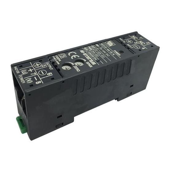
Super-mini Terminal Block Signal Conditioners M5-UNIT
SIGNAL TRANSMITTER
Functions & Features
• Converts a DC input into an isolated DC signal
• High-density mounting
• Power LED
• CE marking for 24 V power
25 (.98)
97
(3.82)
41 (1.61)
mm (inch)
MODEL: M5VS-[1][2]-[3][4]
ORDERING INFORMATION
Specify a code from below for each [1] through [4].
• Code number: M5VS-[1][2]-[3][4]
(e.g. M5VS-4W4W-R/K/Q)
Specify variables.
• Special input and output ranges (For codes Z & 0)
• Specify the specification for option code /Q
(e.g. /C01 /V01)
[1] INPUT
Current
A: 4 – 20 mA DC (Input resistance 249 Ω)
A1: 4 – 20 mA DC (Input resistance 49.9 Ω)
B: 2 – 10 mA DC (Input resistance 499 Ω)
C: 1 – 5 mA DC (Input resistance 1000 Ω)
D: 0 – 20 mA DC (Input resistance 49.9 Ω)
E: 0 – 16 mA DC (Input resistance 61.9 Ω)
F: 0 – 10 mA DC (Input resistance 100 Ω)
G: 0 – 1 mA DC (Input resistance 1000 Ω)
H: 10 – 50 mA DC (Input resistance 20 Ω)
Z: Specify current (See INPUT SPECIFICATIONS)
Voltage
3: 0 – 1 V DC (Input resistance 1 MΩ min.)
4: 0 – 10 V DC (Input resistance 1 MΩ min.)
5: 0 – 5 V DC (Input resistance 1 MΩ min.)
6: 1 – 5 V DC (Input resistance 1 MΩ min.)
4W: -10 – +10 V DC (Input resistance 1 MΩ min.)
5W: -5 – +5 V DC (Input resistance 1 MΩ min.)
0: Specify voltage (See INPUT SPECIFICATIONS)
(CE not available)
SEN TRONIC
AG
Produkte, Support und Service
01: Specify voltage (See INPUT SPECIFICATIONS)
(Choose 01 for CE. Power suffix code R only.)
02: Specify voltage (See INPUT SPECIFICATIONS)
(CE not available)
[2] OUTPUT
Current
A: 4 – 20 mA DC (Load resistance 550 Ω max.)
D: 0 – 20 mA DC (Load resistance 550 Ω max.)
Z: Specify current (See OUTPUT SPECIFICATIONS)
Voltage
1: 0 – 10 mV DC (Load resistance 100 kΩ min.)
(CE not available)
2: 0 – 100 mV DC (Load resistance 100 kΩ min.)
(CE not available)
3: 0 – 1 V DC (Load resistance 100 Ω min.)
4: 0 – 10 V DC (Load resistance 1000 Ω min.)
5: 0 – 5 V DC (Load resistance 500 Ω min.)
6: 1 – 5 V DC (Load resistance 500 Ω min.)
1W: -10 – +10 mV DC (Load resistance 100 kΩ min.)
(CE not available)
2W: -100 – +100 mV DC (Load resistance 100 kΩ min.)
(CE not available)
3W: -1 – +1 V DC (Load resistance 800 Ω min.)
4W: -10 – +10 V DC (Load resistance 8000 Ω min.)
5W: -5 – +5 V DC (Load resistance 4000 Ω min.)
0: Specify voltage (See OUTPUT SPECIFICATIONS)
01: Specify voltage (See OUTPUT SPECIFICATIONS)
(CE not available)
[3] POWER INPUT
AC Power
M: 85 – 264 V AC (Operational voltage range 85 – 264 V,
47 –66 Hz)
(CE not available)
DC Power
R: 24 V DC
(Operational voltage range 24 V ±10 %, ripple 10 %p-p max.)
[4] OPTIONS (multiple selections)
Response Time (0 – 90 %)
blank: Standard (≤ 0.5 sec.)
/K: Fast Response (Approx. 25 msec.)
/F: Fast Response (≤ 1 msec.)
Other Options
blank: none
/Q: Option other than the above (specify the specification)
Rugghölzli 2
Tel. +41 (0)56 222 38 18
CH - 5453 Busslingen
Fax +41 (0)56 222 10 12
MODEL: M5VS
mailbox@sentronic.com
www.sentronic.com
Advertisement
Table of Contents

Subscribe to Our Youtube Channel
Related Manuals for M-system M5VS Series


Summary of Contents for M-system M5VS Series
- Page 1 MODEL: M5VS 01: Specify voltage (See INPUT SPECIFICATIONS) Super-mini Terminal Block Signal Conditioners M5-UNIT (Choose 01 for CE. Power suffix code R only.) 02: Specify voltage (See INPUT SPECIFICATIONS) SIGNAL TRANSMITTER (CE not available) Functions & Features • Converts a DC input into an isolated DC signal [2] OUTPUT •...
-
Page 2: General Specifications
Offset: Max. 1.5 times span SPECIFICATIONS OF OPTION: Q (multiple selections) Load resistance: Output drive 10 mA max.; at ≥1 V COATING (For the detail, refer to M-System's web site.) Max. 1.25 mA output drive for negative voltage /C01: Silicone coating... -
Page 3: Front View
MODEL: M5VS FRONT VIEW Power LED Span Adj. Zero Adj. DIMENSIONS unit: mm (inch) 7.3 (.29) 8–M3.5 SCREW DIN RAIL 35mm wide 25 (.98) 41 (1.61) [3.3 (.13)] • When mounting, no extra space is needed between units. SCHEMATIC CIRCUITRY & CONNECTION DIAGRAM Isolation Low Drift Output... -
Page 4: Signal Transmitter
M5VS SIGNAL TRANSMITTER MODEL BEFORE USE ..COMPONENT IDENTIFICATION Thank you for choosing M-System. Before use, please check Body contents of the package you received as outlined below. Terminal Cover If you have any problems or questions with the product, Spec. -
Page 5: Terminal Connections
M-System’s sole liability, and purchaser’s exclusive remedies, under this warranty are, at M-System’s option, the repair, replacement or refund of the purchase price of any M-System product which is defective under the terms of this warranty. To submit a claim under this warranty, the purchaser must return, at its expense, the defective M-System product to the below address together with a copy of its original sales invoice.
Need help?
Do you have a question about the M5VS Series and is the answer not in the manual?
Questions and answers