Table of Contents
Advertisement
Advertisement
Table of Contents

Related Manuals for Atlantic EPIC 2D Series


Summary of Contents for Atlantic EPIC 2D Series
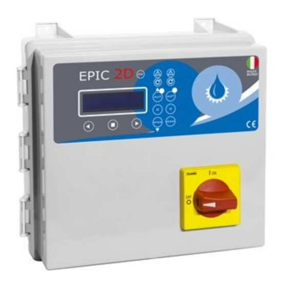
- Page 1 MADE IN ITALY EPIC 2D Installation ad use manual 0,37÷15 RANGE 0,50÷20...
- Page 2 Index EPIC 2D Introduction 1.1 PRESENTATION pag. 3 1.2 DESCRIPTION pag. 3 1.3 HANDLING pag. 3 Safety informations 2.1 WARNINGS pag. 4 2.2 CAUTION pag. 4 Installation 3.1 ASSEMBLING pag. 5 3.2 ELECTRICAL CONNECTIONS pag. 6 EPIC 2D 3.3 ADJUSTMENTS AND SETTINGS pag.
- Page 3 If any damage is visible, inform an Atlantic dealer as soon as possible, no later then five days from the delivery date.
- Page 4 Safety informations EPIC 2D 2.1 WARNINGS RISK OF ELECTRIC SHOCK Failure to follow the instructions in this manual, carries a risk of electric shock. RISK FOR PEOPLE AND PROPERTY Failure to follow the prescriptions in this manual, carries a risk of damage to persons and/or property.
- Page 5 Installation EPIC 2D 3.1 ASSEMBLING Fix the control panel for a stable support with If use an electric screwier pay attention not to screws and screw anchor using the holes spoil the thread or the screws. arranged in the box (pic. 1) or the fixing bracket if present.
- Page 6 Installation EPIC 2D 3.2 ELECTRICAL CONNECTIONS EPIC 2D 230 1 2 3 4 5 6 N L C N L C 230 V 50÷60 Hz 2 3 C...
- Page 7 Installation EPIC 2D EPIC 2D 400 400 V 50÷60 Hz 2 3 C...
- Page 8 Installation EPIC 2D 3.3 ADJUSTMENTS AND SETTINGS (INITIALIZATION) CONTROL PANEL TURN ON >LANGUAGE >ITA After making all the electrical connections, initial message to appear on the display. switch on the control panel and wait for the LANGUAGE SETTING (OBLIGATORY) Step 1 Step 2 Step 3 >LANGUAGE...
- Page 9 Installation EPIC 2D AUTOTUNING (OBLIGATORY) Step 5 Step 6 Step 7 AUTOTUNING: P1 AUTOTUNING: P1 CONFIRM DATA? PUSH CONFIRM xxxV To start the self-learning of the pump 1 data, Before starting the self-learning type reply (step 5). procedure, it is necessary to check with a tester that the For the final confirmation of the data (step 7) type mains voltage corresponds to...
- Page 10 Installation EPIC 2D 3.4 ADJUSTMENTS AND SETTINGS (ADVANCED MENU) ACCESS TO ADVANCED MENU DIP-SWITCH 2 The control panel is set as standard with the dip-switch 2 in the “OFF” position. To access the “ADVANCED MENU” and modify the various parameters, switch off the control panel and set dip-switch 2 to “ON”.
- Page 11 Installation EPIC 2D M01 UTILITY ACCESS TO FUNCTION MODIFIED PARAMETERS LANGUAGE >M01 UTILITY Language selection M02 GENERAL START DELAY Control panel switch-on delay after restart (in sec.) MANUAL KEYPAD Possibility of operating the “MAN” button in stable or unstable mode ON: unstable OFF: stable CHANGE LANGUAGE...
- Page 12 Installation EPIC 2D CHANGE “MAN” BUTTON (STABLE/UNSTABILE) M01 UTILITY >MAN. MODALITY MAN. MODALITY >MAN. MODALITY >OFF MAN. MODALITY M01 UTILITY >EXIT >ON >MAN. MODALITY...
- Page 13 Installation EPIC 2D M02 GENERAL ACCESS TO FUNCTION MODIFIED PARAMETERS PUMP START DELAY M01 UTILITY PUMP STOP DELAY >M02 GENERAL PUMPS ALTERNATION TIME ON MAX Max continuous operation of the pump. Received consent from the level control, the pump switches on and operates for a maximum duration set by the user (in min.) The parameter is not active if the value is 0 min.
- Page 14 Installation EPIC 2D CHANGE PUMPS ALTERNATION M02 GENERAL >ALTERNATION ALTERNATION >ALTERNATION >ON ALTERNATION M02 GENERAL >EXIT >OFF >ALTERNATION CHANGE TIME ON MAX M02 GENERAL >TIME ON MAX TIME ON MAX >TIME ON MAX >001 TIME ON MAX M02 GENERAL >EXIT >001 >TIME ON MAX “TIME ON MAX”...
- Page 15 Installation EPIC 2D M03 NET CONTROL ACCESS TO FUNCTION MODIFIED PARAMETERS NOMINAL VOLTAGE M02 GENERAL MINIMUM VOLTAGE >M03 NET CONTROL MAXIMUM VOLTAGE NOMINAL FREQUENCY FREQUENCY RANGE CHANGE NOMINAL VOLTAGE M03 NET CONTROL >NOM. VOLTAGE NOM. VOLTAGE >NOM. VOLTAGE VOLT >XXX VOLT NOM.
- Page 16 Installation EPIC 2D CHANGE MAXIMUM VOLTAGE M03 NET CONTROL >MAX VOLTAGE MAX VOLTAGE >MAX VOLTAGE >110 MAX VOLTAGE M03 NET CONTROL >EXIT >110 >MAX VOLTAGE CHANGE NOMINAL FREQUENCY M03 NET CONTROL >NOM. FREQUENCY NOM. FREQUENCY >NOM. FREQUENCY >50 NOM. FREQUENCY M03 NET CONTROL >EXIT >50...
- Page 17 Installation EPIC 2D M04 PUMP 1 / M05 PUMP 2 ACCESS TO FUNCTION MODIFIED PARAMETERS AUTOTUNING It allows the self-learning of the data to be carried out again >M04 PUMP 1 NOMINAL CURRENT M05 PUMP 2 Set nominal/operating current of the pump MINIMUM AMPERAGE Current setting min.
- Page 18 Installation EPIC 2D CHANGE MINIMUM AMPERAGE M04 PUMP 1 >MIN AMPERAGE MIN AMPERAGE >MIN AMPERAGE >085 MIN AMPERAGE M04 PUMP 1 >EXIT >XXX >MIN AMPERAGE CHANGE MAXIMUM AMPERAGE M04 PUMP 1 >MAX AMPERAGE MAX AMPERAGE >MAX AMPERAGE >130 MAX AMPERAGE M04 PUMP 1 >EXIT >XXX...
- Page 19 Installation EPIC 2D M06 PROGRAM ACCESS TO FUNCTION MODIFIED PARAMETERS OPERATION Emptying selection “EMPTY” or filling ”FILL“ M05 PUMP 2 TYPE >M06 PROGRAM Selection of clear or dirty water types SELF HOLDING Mostly used for waste water applications: 4 floating switches has been used (G1 stop the pumps, G2 start pump 1, G3 start pump 2, G4 max level alarm and start both pumps) SELF HOLDING OPERATION...
- Page 20 Installation EPIC 2D SELF HOLDING M06 PROGRAM >SELF HOLDING SELF HOLDING >SELF HOLDING >ON SELF HOLDING M06 PROGRAM >EXIT >OFF >SELF HOLDING BMS SETTING M06 PROGRAM >BMS >BMS >OFF M06 PROGRAM >EXIT >ON >BMS MULTI TANK SETTING M06 PROGRAM >MULTI TANK MULTI TANK >MULTI TANK >OFF...
- Page 21 Installation EPIC 2D M07 SENSOR (sensor/trasducer 4÷20 mA) ACCESS TO FUNCTION MODIFIED PARAMETERS PARAMETERS Setting unit of measure (mt/bar) M06 PROGRAM FULL SCALE >M07 SENSOR Set the full scale value specified by the manufacturer of the sensor used (serial value 160.0) MINIMUM LEVEL Parameter active only with unit of measure in mt MAXIMUM LEVEL...
- Page 22 Installation EPIC 2D SET MINIMUM LEVEL M07 SENSOR >MIN LEVEL MIN LEVEL >MIN LEVEL 005.5 >005.0 MIN LEVEL M07 SENSOR >EXIT >005.0 >MIN LEVEL SET MAXIMUM LEVEL M07 SENSOR >MAX LEVEL MAX LEVEL >MAX LEVEL 100.0 >100.0 MAX LEVEL M07 SENSOR >EXIT >100.0 >MAX LEVEL...
- Page 23 Installation EPIC 2D PUMP 1 STOP M07 SENSOR >P1 STOP P1 STOP >P1 STOP 020.0 >020.0 P1 STOP M07 SENSOR >EXIT >XXX.X >P1 STOP PUMP START / STOP SETTING 2 It is necessary to carry out the same procedure to set the values of the “START PUMP 2”...
- Page 24 Installation EPIC 2D M08 TIMER ACCESS TO FUNCTION MODIFIED PARAMETERS ENGAGE TIMER T1 TIMER T1 ON M07 SENSOR Setting the working minutes of the pump 1 >M08 TIMER TIMER T1 OFF Setting the pump pause minutes ENGAGE TIMER T2 TIMER T2 ON Setting the working minutes of the pump 2 TIMER T2 OFF Setting the pump pause minutes...
- Page 25 Installation EPIC 2D TIMER T1 OFF M08 TIMER >timer t1 off timer t1 off >timer t1 off 0000 >0000 timer t1 off M08 TIMER >USCITA >xxxx >timer t1 off TIMER SETTING T2 ON / TIMER T2 ON The same procedure must be followed to set the values of the “TIMER T2 ON” and “TIMER T2 OFF”...
- Page 26 Installation EPIC 2D 3.5 TRIMMER SETTINGS To change manually the threshold protections, PROTECTION DELAY interrupt the power supply to the control The pump protection switching panel and work on the trimmers, please delay has been set at 5 sec. following the below instructions: TRIMMER SETTING TRIMMER 1: PROBE SENSITIVITY CHANGE Probe sensivity (CLC) and water in oil chamber sensor trimmer...
- Page 27 General use EPIC 2D 4.1 KEYPAD AND LIGHTS INDICATIONS CONTROL PANEL blue light indicating power network presence and powered panel. ALARM red light to indicate a general alarm and pump stop. (min e max Amp, min e max V, min e max level, motor klixon, water in oil chamber, phase failure). START green light to indicate pump start;...
- Page 28 General use EPIC 2D 4.2 ALARMS The control panel signals a series of alarms that All alarms are displayed on the panel (red LED may occur during operation. Some of these stop flashing), while the display shows the code/alarms the pumps, while others are only displayed. occurred until the cancellation by the operator.
- Page 29 General use EPIC 2D ALARM WITH STOP PUMP Following the detection of an alarm and the consequent blocking of the pump, the control panel provides the following operations: • Try the first restart after 5 min. • In case of a negative result, make another attempt after 30 min. and 3 other attempts with intervals of 60 min.
- Page 30 General use EPIC 2D 4.3 TYPICAL INSTALLATIONS 4÷20 4÷20 start start/stop start/stop start stop 4÷20 4÷20 start/stop start/stop start start stop 4÷20 input for 4÷20 mA sensor or pressure transducer pressure transducer 2/3/C input for level probes float switch for clear water input for water in oil chamber sensor/water leakage float switch for waste water input for motor klixon...
- Page 31 General use EPIC 2D 4÷20 4÷20 start/stop start/stop start/stop start/stop 4÷20 4÷20 P1-P2 start/stop 4÷20 mA piezo 4÷20 mA P1-P2 start/stop 4÷20 input for 4÷20 mA sensor or pressure transducer pressure transducer 2/3/C input for level probes float switch for clear water input for water in oil chamber sensor/water leakage float switch for waste water input for motor klixon...
- Page 32 Maintenance EPIC 2D 5.1 PUMPS STOP MODE BUTTON STOP The motor stops when the “MANUAL” button is MANUAL released or once you digit the 0 button. When the input commands are disable/non active once AUTOMATIC you digit the 0 button. Turning the main switch interlocking door in “OFF”...
- Page 33 Certifications EPIC 2D 6.1 CERTIFICATE OF CONFORMITY The Manufacturer: Atlantic Power Control S.r.l.s Via E. Fermi, 10 - 35020 Polverara (PD) - ITALIA DECLARES UNDER IS OWN RESPONSIBILITY THAT THE FOLLOWINGS CONTROL PANELS: EPIC 2D -230 e EPIC 2D -400...
- Page 34 Note EPIC 2D...
- Page 35 Note EPIC 2D...
- Page 36 ATLANTIC POWER CONTROL S.r.l.s. Via E. Fermi, 10 35020 Polverara (PD) Italy Tel +39 0495855425 www.atlanticontrol.com info@atlanticontrol.com...
Need help?
Do you have a question about the EPIC 2D Series and is the answer not in the manual?
Questions and answers