Table of Contents
Advertisement
Quick Links
Advertisement
Table of Contents

Related Manuals for Atlantic EPIC 1D

Summary of Contents for Atlantic EPIC 1D
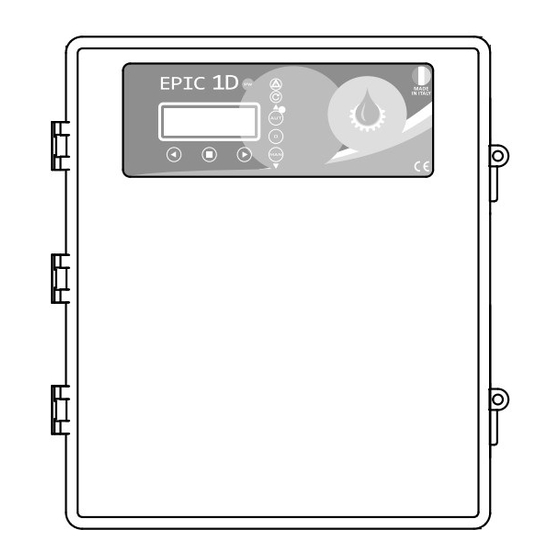
- Page 1 MADE IN ITALY EPIC 1D Installation ad use manual 0,37÷15 RANGE 0,50÷20...
- Page 2 Index EPIC 1D Introduction 1.1 PRESENTATION pag. 3 1.2 DESCRIPTION pag. 3 1.3 HANDLING pag. 3 Safety informations 2.1 WARNINGS pag. 4 2.2 CAUTION pag. 4 Installation 3.1 ASSEMBLING pag. 5 3.2 ELECTRICAL CONNECTIONS pag. 6 EPIC 1D 3.3 ADJUSTMENTS AND SETTINGS pag.
- Page 3 If any damage is visible, inform an Atlantic dealer as soon as possible, no later then five days from the delivery date.
-
Page 4: Safety Information
• (400V ± 10% 50/60Hz x il EPIC 1D -400/...) protected. The line must be protected with an • (230V ± 10% 50/60Hz x il EPIC 1D -230) Earth leackage and magnetic switch measured in accordance with the regulations locally in force. -
Page 5: Installation
Installation EPIC 1D 3.1 ASSEMBLING Fix the control panel for a stable support with If use an electric screwier pay attention not to screws and screw anchor using the holes spoil the thread or the screws. arranged in the box. -
Page 6: Electrical Connections
Installation EPIC 1D 3.2 ELECTRICAL CONNECTIONS EPIC 1D 230 N L C 230 V 50÷60 Hz 2 3 C... - Page 7 Installation EPIC 1D EPIC 1D 400 400 V 50÷60 Hz 2 3 C...
- Page 8 Installation EPIC 1D 3.3 ADJUSTMENTS AND SETTINGS (INITIALIZATION) CONTROL PANEL TURN ON >LANGUAGE >ITA After making all the electrical connections, initial message to appear on the display. switch on the control panel and wait for the LANGUAGE SETTING (OBLIGATORY) Step 1...
-
Page 9: Preset Parameters
Installation EPIC 1D AUTOTUNING (OBLIGATORY) Step 5 Step 6 Step 7 AUTOTUNING: P1 AUTOTUNING: P1 CONFIRM DATA? PUSH CONFIRM xxxV To start the self-learning of the pump data, Before starting the self-learning type reply (step 5). procedure, it is necessary to... - Page 10 Installation EPIC 1D 3.4 ADJUSTMENTS AND SETTINGS (ADVANCED MENU) ACCESS TO ADVANCED MENU DIP-SWITCH 2 The control panel is set as standard with the dip-switch 2 in the “OFF” position. To access the “ADVANCED MENU” and modify the various parameters, switch off the control panel and set dip-switch 2 to “ON”.
- Page 11 Installation EPIC 1D M01 UTILITY ACCESS TO FUNCTION MODIFIED PARAMETERS LANGUAGE (default: as selected) Language selection >M01 UTILITY START DELAY (default: 2 sec.) M02 GENERAL Control panel switch-on delay after restart (in sec.) MANUAL KEYPAD (default: OFF) Possibility of operating the “MAN” button in stable or...
- Page 12 Installation EPIC 1D CHANGE “MAN” BUTTON (STABLE/UNSTABILE) M01 UTILITY >MAN. MODALITY MAN. MODALITY >MAN. MODALITY >OFF MAN. MODALITY M01 UTILITY >EXIT >ON >MAN. MODALITY CHANGE MAX LEVEL ALARM DELAY M01 UTILITY >MAX LEV ALL.DEL MAX LEV ALL.DEL >MAX LEV ALL.DEL >OFF...
- Page 13 Installation EPIC 1D M02 GENERAL ACCESS TO FUNCTION MODIFIED PARAMETERS PUMP START DELAY (default: 4 sec.) M01 UTILITY Set the pump start delay >M02 GENERAL PUMP STOP DELAY (default: 1 sec.) Set the pump stop delay CHANGE START DELAY M02 GENERAL >START DELAY...
-
Page 14: Modified Parameters
Installation EPIC 1D M03 NET CONTROL ACCESS TO FUNCTION MODIFIED PARAMETERS NOMINAL VOLTAGE (default: autotuning read) M02 GENERAL Set the nominal voltage >M03 NET CONTROL MINIMUM VOLTAGE (default: 90%) Set the minimum voltage MAXIMUM VOLTAGE (default: 110%) Set the maximum voltage... - Page 15 Installation EPIC 1D CHANGE MAXIMUM VOLTAGE M03 NET CONTROL >MAX VOLTAGE MAX VOLTAGE >MAX VOLTAGE >110 MAX VOLTAGE M03 NET CONTROL >EXIT >110 >MAX VOLTAGE CHANGE NOMINAL FREQUENCY M03 NET CONTROL >NOM. FREQUENCY NOM. FREQUENCY >NOM. FREQUENCY >50 NOM. FREQUENCY M03 NET CONTROL >EXIT...
-
Page 16: Auto Tuning
Installation EPIC 1D M04 PUMP 1 ACCESS TO FUNCTION MODIFIED PARAMETERS AUTOTUNING It allows the self-learning of the data to be carried out again >M04 PUMP 1 NOMINAL CURRENT (default: autotuning read) M06 PROGRAM Set nominal/operating current of the pump... - Page 17 Installation EPIC 1D CHANGE MINIMUM AMPERAGE M04 PUMP 1 >MIN AMPERAGE MIN AMPERAGE >MIN AMPERAGE >085 MIN AMPERAGE M04 PUMP 1 >EXIT >XXX >MIN AMPERAGE CHANGE MAXIMUM AMPERAGE M04 PUMP 1 >MAX AMPERAGE MAX AMPERAGE >MAX AMPERAGE >130 MAX AMPERAGE M04 PUMP 1 >EXIT...
- Page 18 Installation EPIC 1D φ CHANGE MIN COS φ φ M04 PUMP 1 >MIN. COS MIN. COS φ >MIN. COS X.XX >X.XX φ MIN. COS M04 PUMP 1 >EXIT φ >X.XX >MIN. COS...
- Page 19 Installation EPIC 1D M06 PROGRAM ACCESS TO FUNCTION MODIFIED PARAMETERS OPERATION (default: EMPTY) Emptying selection “EMPTY” or filling ”FILL“ M04 PUMP 1 TYPE (default: POTABLE) >M06 PROGRAM Selection between clear (potable) and waste water SELF HOLDING (default: ON) Possibility to carry out a rapid emptying of the tank,...
- Page 20 Installation EPIC 1D SELF HOLDING M06 PROGRAM >SELF HOLDING SELF HOLDING >SELF HOLDING >ON SELF HOLDING M06 PROGRAM >EXIT >OFF >SELF HOLDING BMS SETTING M06 PROGRAM >BMS >BMS >OFF M06 PROGRAM >EXIT >ON >BMS...
- Page 21 Installation EPIC 1D M07 SENSOR (sensor/trasducer 4÷20 mA) ACCESS TO FUNCTION MODIFIED PARAMETERS PARAMETERS (default: OFF) Setting unit of measure (mt/bar/celsius) M06 PROGRAM FULL SCALE (default: 160.0) >M07 SENSOR Set the full scale value specified by the manufacturer of the sensor used (serial value 160.0) MINIMUM LEVEL (default: 5.0)
-
Page 22: Set Minimum Level
Installation EPIC 1D SET MINIMUM LEVEL M07 SENSOR >MIN LEVEL MIN LEVEL >MIN LEVEL 005.5 >005.0 MIN LEVEL M07 SENSOR >EXIT >005.0 >MIN LEVEL SET MAXIMUM LEVEL M07 SENSOR >MAX LEVEL MAX LEVEL >MAX LEVEL 100.0 >100.0 MAX LEVEL M07 SENSOR >EXIT... - Page 23 Installation EPIC 1D PUMP 1 STOP M07 SENSOR >P1 STOP P1 STOP >P1 STOP 020.0 >020.0 P1 STOP M07 SENSOR >EXIT >XXX.X >P1 STOP IMPORTANT! For the mt and celsius parameters you can select the “FILL” and “EMPTY” programs (see page 19) •...
- Page 24 Installation EPIC 1D M08 TIMER ACCESS TO FUNCTION MODIFIED PARAMETERS ENGAGE TIMER T1 (default: OFF) M07 SENSOR TIMER T1 ON (default: 0 min.) >M08 TIMER Setting the working minutes of the pump TIMER T1 OFF (default: 0 min.) Setting the pause minutes of the pump...
- Page 25 Installation EPIC 1D TIMER T1 OFF M08 TIMER >timer t1 off timer t1 off >timer t1 off 0000 >0000 timer t1 off M08 TIMER >USCITA >xxxx >timer t1 off...
- Page 26 Installation EPIC 1D 3.5 TRIMMER SETTINGS To change manually CLC sensitivity and water PROTECTION DELAY in the oil chamber, interrupt the power supply The pump protection switching to the control panel and work on the trimmers, delay has been set at 5 sec.
-
Page 27: General Use
General use EPIC 1D 4.1 KEYPAD AND LIGHTS INDICATIONS CONTROL PANEL blue light indicating power network presence and powered panel. ALARM red light to indicate a general alarm and pump stop. (min and max Amp, min and max V, min and max level, motor klixon, water in oil chamber, phase failure, max starts par hour). - Page 28 General use EPIC 1D 4.2 ALARMS The control panel signals a series of alarms that All alarms are displayed on the panel (red led may occur during operation. Some of these stop flashing), while the display shows the code/alarms the pumps, while others are only displayed.
-
Page 29: Delete Alarm
General use EPIC 1D ALARM WITH STOP PUMP Following the detection of an electrical alarm and the consequent blocking of the pump, the control panel does the following operations: • After 30 minutes try to restart the pump • In case of a negative feedback, it makes further attempts every 30 minutes N.B.: Restart attempts will be made only if the panel receives the start consent... -
Page 30: Typical Installations
General use EPIC 1D 4.3 TYPICAL INSTALLATIONS Picture 1 Picture 2 4÷20 4÷20 start/stop start/stop Picture 3 Picture 4 4÷20 4÷20 start/stop lev. 4÷20 input for 4÷20 mA sensor or pressure transducer pressure transducer 2/3/C input for level probes float switch for clear water... - Page 31 General use EPIC 1D Picture 5 Picture 6 4÷20 4÷20 start/stop start stop Picture 7 Picture 8 4÷20 4÷20 start/stop 4÷20 mA piezo 4÷20 mA start/stop 4÷20 input for 4÷20 mA sensor or pressure transducer pressure transducer 2/3/C input for level probes...
-
Page 32: Maintenance
0 button. Turning the main switch interlocking door in “OFF” position. 5.2 SERVICE EPIC 1D does not require any routine maintenance DANGER! provided that their working limits are observed. Make sure that EPIC 1D is Any maintenance operations must be performed... -
Page 33: Certificate Of Conformity
Atlantic Power Control S.r.l.s Via E. Fermi, 10 - 35020 Polverara (PD) - ITALY DECLARES UNDER IS OWN RESPONSIBILITY THAT THE FOLLOWINGS CONTROL PANELS: EPIC 1D -230 e EPIC 1D -400 ARE IN CONFORMITY WITH COMMUNITY DIRECTIVES REGARDING: • European •... - Page 34 Notes EPIC 1D...
- Page 35 Notes EPIC 1D...
- Page 36 ATLANTIC POWER CONTROL S.r.l.s. Via E. Fermi, 10 35020 Polverara (PD) Italy Tel +39 0495855425 CERTIFIED www.atlanticontrol.com 9001 - 14001 45001 info@atlanticontrol.com...