Table of Contents
Advertisement
ISO 9001
EN ISO 13485
Digital Pneumatic Tourniquet system
USER MANUAL
Read this manual carefully. This manual is for user's safety
and previewing any property-loss. Before using our device,
Indications
please read this manual inevitably.
for safety use
This product is medical device using under doctor's
instructors.
UserManual_DTS-3000_170223_인증용.indd 1
2017-02-23 오후 2:06:03
Advertisement
Table of Contents

Subscribe to Our Youtube Channel
Related Manuals for DAESUNG MAREF DTS-3000


Summary of Contents for DAESUNG MAREF DTS-3000
- Page 1 ISO 9001 EN ISO 13485 Digital Pneumatic Tourniquet system USER MANUAL Read this manual carefully. This manual is for user's safety and previewing any property-loss. Before using our device, Indications please read this manual inevitably. for safety use This product is medical device using under doctor's instructors.
- Page 2 1. Information 1-1. DTS-3000 Introduction CONTENTS 1-2. Intended use 1-3. Target treatment group and diseases 1-4. Expected except group of treatment 1-5. Side effect 2. Information on Safety and Handling 2-1. Operation of the device 2-2. Indications for use 2-3. Cuff safekeeping and maintenance 2-4.
- Page 3 9-2. Guidance and manufacturer’s declaration – electromagnetic immunity 9-3. Guidance and manufacturer’s declaration – electromagnetic immunity 9-4. Recommended separation distances between portable and mobile RF communications equipment and the DTS-3000 10. Symbols Information 10-1. Symbols Information (Device) 10-2. Symbols Information (Set Box) 10-3.
-
Page 4: Intended Use
Information 1-1. DTS-3000 Introduction Thank you for purchasing DTS-3000. DTS-3000 is the surgery device blocking blood flow by wrapping the limbs with cuff and inflating the cuff. Thus, this device shall be applied under the instruction of a doctor. This device has two channels with 4 ports that can connect two double cuffs at the same time. - Page 5 - Total wrist joint replacement - Replacement of joints in the fingers - Knee joint replacements 1-4. Expected except group of treatment - Open fractures of the leg - Post-traumatic lengthy hand reconstruction - Severe crushing injuries - Elbow surgery (where there is excess swelling) - Severe hypertension - Skin grafts in which all bleeding points must be readily distinguished - Compromised vascular circulation, e.g.peripheral artery disease.
-
Page 6: Operation Of The Device
Information on Safety and Handling 2-1. Operation of the device - In case of any abnormal smell, stop using this device. Turn off the power immediately and pull the power plug out of the outlet. And contact the Service Center. Continuing application may cause fire or electric shock. - Unplug out the device in case of thunder, lightning, or power failure. -
Page 7: Indications For Use
- This Product is used to connect to a power source that is grounded. If you are connecting to a power source that is not grounded, it may occur to malfunction and problems protection circuit works when the device shorted. - Do not use oil, benzene, alcohol, or any other chemicals to clean the device or cuff. - Page 8 LOP sensor to recognize. - A cuff shall be the exclusive cuff for the model of DAESUNG MAREF. Do not use any cuffs from other manufacturers or for other models of DAESUNG MAREF.
- Page 9 - Select the proper cuffs depending on patients, application areas or types of operations. Improper cuffs may drop the efficiency of hemostasis or cause the failure in getting the intended effects from operations. - Do not use the device in the area with strong magnetic field or electromagnetic field.
- Page 10 2-4. Device safekeeping and maintenance - Be cautious not to bend or fold the hose. It may cause improper operation. Immediately request maintenance to a vendor or customer service enter in case of any damage of the compressor case. (Doing so may lead to a risk of fire.) - Prevent clips, staples, metals, food or liquid from getting into this device.
- Page 11 - The performance of battery may be degraded when it is not used for a long time. Keeping the discharged battery for a long time may increase the risk of short circuit. Shorted battery may reduce the battery life and cause safety accidents.
- Page 12 2-6. Cleaning 2-6-1. How to clean the device - If any foreign materials get on the device, first turn off the device and use a soft cloth to wipe the device with a bit of water or a neutral detergent. (It may cause discoloration, damage or malfunction.) - If you sanitize product, first turn off the device and wipe off with soft cotton using neutral detergent.
- Page 13 62.2%. Information for treatment facilities shall be made available to centres which prepare for re- use and treatment and recyling facilities by producers of EEE. DAESUNG MAREF, whenever, is prepared to provide. The symbol indicating separate collection for EEE consists of the cross-out wheeled bin, as shown below.
-
Page 14: Storage Conditions
2-7-2. Correct disposal of batteries in this product (1) Crossed-out wheeled bin applies to all batteries; (2) Chemical symbols (Hg, Cd, Pb), indicating the heavy metal content of batteries, apply to batteries containing more than a given amount of these substances; •... -
Page 15: Product Package
Product package 3-1. Device part User manual Main device Power code Air Hose (Blue) 1EA Air Hose (Red) 1EA Air Hose (Gray) 2EA UserManual_DTS-3000_170223_인증용.indd 15 2017-02-23 오후 2:06:04... - Page 16 3-2. Cuff part Select and purchase the cuffs depending on user's status or application areas. Single Cuff Double Cuff Cone Single Cuff Cone Double Cuff Rubber Bladder Cuff * The cuff is a consumable product. * The cuff is defined as the mounting part in IEC 60601-1. UserManual_DTS-3000_170223_인증용.indd 16 2017-02-23 오후...
- Page 17 3-3. LOP Sensor The LOP sensor is defined as the mounting part in IEC 60601-1. UserManual_DTS-3000_170223_인증용.indd 17 2017-02-23 오후 2:06:05...
-
Page 18: Product Description
Product description 4-1. Device specifications Items Specification Model DTS-3000 Protection Type Class IIa, BF-type Device Rated Voltage AC100-240V, 50/60Hz Power Consumption 80VA Rated Fuse T3.15A/250V * Setting pressure 20~700mmHg ± 4mmHg should be operated Setting Pressure (Unit : 1, 5mmHg) under doctor's instructions. - Page 19 4-3. Cuff specifications Part no. Cuff names and size Part no. Cuff names and size DTC-S02 SINGLE 40 X 7cm CUFF DTC-D05 DOUBLE 80 X 15cm CUFF DTC-S04 SINGLE 52 X 7.5cm CUFF DTC-D06 DOUBLE 107 X 15cm CUFF DTC-S05 SINGLE 61 X 9cmCUFF DTC-D07 DOUBLE 57 X 15cm CUFF...
-
Page 20: Names And Functions Of Parts
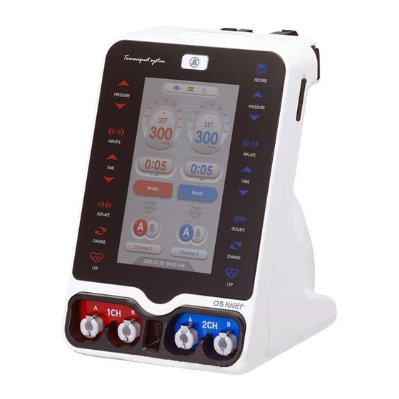
4-4. Names and Functions of Parts Name Function LCD Screen Display the operating status of the device. - Socket for inserting red hose into 1ch when using single cuff. 1CH Air Socket - Socket for inserting red hose and gray hose into 1ch when ... -
Page 21: Names And Functions Of Control Panel
4-5. Names and Functions of Control Panel Name Function Control of Pressure of 1CH The previous setting is saved and displayed. The pressure can be adjusted from 20 to 700mmHg depending on patient’s status and application areas. Set the pressure using the Pressure button ( , ). Pressure Press for about 3 seconds. - Page 22 Inflation of the cuff of 1CH Press the Inflate button long (3 seconds) to apply preset pressure to a cuff. Inflation When pressure is applied to a cuff, LCD displays Button When pressure reaches to the preset value, displayed. Time setting of 1CH The previous value is saved and displayed.
- Page 23 Then, LOP automatically estimates and notifies the proper pressure for a patient. To start, press the Inflate button to 1CH LOP activate. The icon below is activated on the LCD Button during LOP measurement. LOP icon color is changed as shown below.
- Page 24 Deflate the cuff of 2CH Deflate For deflating a cuff, press the Deflate button long (3seconds). Button LCD displays during deflating. Change the hemostasis area while using double cuff of 2CH When operation continues for a long time, change the hemostasis area while using double cuff to prevent damage of 2CH Cuff skin, nerve or muscle.
-
Page 25: Lcd Screen
4-6. LCD Screen AC CordIndication Error Indication Icon Screen Battery Remaining Icon Channel 1 Channel 2 Pressure Indication Pressure Indication Screen Channel 1 Channel 2 Time Indication Screen Time Indication Screen Channel 1 Channel 2 Operation Status Screen Operation Status Screen Channel 1 Channel 2 LOP Sensor Icon... - Page 26 2) Power Status - Display the power status on the top of LCD. 3) Battery Status - Display the battery status in four steps depending on the charging amount. The battery is automatically charged when AC power is supplied. Full Charge External power connection Medium Charge Charge Required...
- Page 27 Product use and procedure 5-1. Before using a device Use this device in accordance with the instruction from a doctor. Select proper application area, types of cuffs and pressure level in consideration of a patient’s status and operation area. Improper application may have adverse impact to patients during operation.
-
Page 28: Cuff Connection
5-4. Cuff connection 5-4-1. Single cuff - Connect the air hose to the channel until you hear the ‘click’ sound. (When the Lock Pin is not pressed in the air socket in the device, press the top to open it with the sound ‘click’) - For separating the air hose from the device, pull the air hose as pressing the top of air socket, ... - Page 29 5-4-2. Double cuff connection - Connect the air hose to the channel until you hear the ‘click’ sound. (When the Lock Pin is not pressed in the air socket in the device, press the top to open it with the sound ‘click’) - For separating the air hose from the device, pull the air hose as pressing the top of air socket, and the air hose is easily removed.
- Page 30 5-5. LOP connection - Connect the port of LOP Sensor to the device. - Put the LOP Sensor to the index finger or the second toe of the limb where the cuff is applied. Put a finger or a toe deep into the sensor.
-
Page 31: Alarm Messages
Troubleshooting 6-1. Alarm messages Alarm Code Description Actions - Take the follow-up actions in accordance with the instructions from a doctor. - Finish alarm rings after the set time. Indicate the set (However, the device is not turned off time is over. and cuffs are not deflated.) - Press the Deflate button to deflate the cuffs. -
Page 32: General Troubleshooting
6-2. General Troubleshooting Problem Cause Solution Power connection Check that the plug is correctly inserted into alarm the power outlet Check if your power supply is in the range of No electric power Rated power AC100-240V, 50/60Hz Check if FUSE is in the state of shortcut. FUSE shortcut (FUSE is located inside AC INLET.) Power on but not... -
Page 33: Maintenance And Safety Instructions
4) Press Power button with long key to quit Maintenance mode. 7-2. Explanation of each test 7-2-1. Version verification - DTS-3000 uses both Main board and Sub board in general. Main board : It is mainly controls Drive that manipulate LCD display, Button input control, LOP control, SD DATA SAVE. -
Page 34: Power Display
7-2-2. Power display Display Status Test method AC is not connected. Reboot the device in Maintenance mode while battery is in it then check if AC connection status shows in the right way as AC connection goes and disconnection goes. AC is connected 7-2-3. -
Page 35: Button Check
7-2-4. Button check Display Status Test method Condition that - Verify if selected button indicates button is not on Display or not and make sure pressed firmly. if it is matched with images on the left. - PRESSURE, INFLATE, TIME, Condition that DEFLATE, CHANGE, LOP, button is pressed... - Page 36 Display Test method The test starts from CH1 after inflating for 10 seconds whether there pressure stays or not. If pressure sensor does not recognize pressure, then the machine decides there is problem with Solenoid and shows solenoid error. The machine does not perform following test. Sensor check / Leak check test.
- Page 37 1 The Forrest Units, Hennock Road East Exeter, EX2 8RU, UK Tel: +44-1392-829500 Fax: +44-1392-823232 Device : Digital Pneumatic Tourniquet system Model : DTS-3000 Weight : 3Kg (Only Body) Dimension : 180(W) x 200(D) x 260(H) mm Power consumption : 80VA Power source : AC100 - 240V, 50/60Hz Battery : DC 14.4V, 2600mAh...
- Page 38 Side of Device KEEP POWER CORD PLUGGED IN. BATTERY ONLY FOR USE DURING POWER EMERGENCY OR TEMPORARY PATIENT TRANSPORT. ATTENTION : UNIT SHOULD BE PLUGGED IN 24 HOURS BEFORE USE TO PROPERLY CHARGE BATTERIES. Back of Device Back of Device UserManual_DTS-3000_170223_인증용.indd 38 2017-02-23 오후...
-
Page 39: Guidance And Manufacturer's Declaration - Electromagnetic Immunity
9-1. Guidance and manufacturer’s declaration - electromagnetic emissions The DTS-3000 is intended for use in the electromagnetic environment specified below. The customer or the user of DTS-3000 should assure that it is used in such an environment. Emissions test Compliance... - Page 40 Voltage dips, short 40% U or hospital environment. If the (60% dip in U interruptions and (60% dip in U user of the DTS-3000 requires for 5cycles voltage variations on for 5cycles continued operation during 70% U power supply input...
- Page 41 9-3. Guidance and manufacturer’s declaration – electromagnetic immunity The DTS-3000 is intended for use in the electromagnetic environment specified below. The customer or the user of the DTS-3000 should assure that it is used in such an environment. IEC 60601 Compliance...
- Page 42 RF transmitters, an electromagnetic site survey should be considered. If the measured field strength in the location in which the DTS-3000 is used exceeds the applicable RF compliance level above, the DTS-3000 should be observed to verify normal operation.
- Page 43 R F communications equipment and the DTS-3000 The DTS-3000 is intended for use in an electromagnetic environment in which radiated RF disturbances are controlled. The customer or the user of the DTS-3000 can help prevent electromagnetic interference by maintaining a minimum distance bet ween portable and mobile RF communications equipment (transmitters) and the DTS-3000 as recommended below, according to the maximum output power of the communications equipment.
-
Page 44: Symbols Information
Symbols Information 10-1. Symbols Information (Device) Symbols Explanation Reference EN 980 Manufacturer 5.12 EN 980 European Representative 5.13 EN 980 Data of Manufacture EN 980 Serial Number Symbol that indicates electrical and electronic components which must be EN 50419 collected separately. The official mark of Europe CE logo Certificate... - Page 45 Deflate Button Custom Symbol Cuff Change Button Custom Symbol LOP Button Custom Symbol Record Button Custom Symbol IEC 60878 "ON" (power) 5007 IEC 60878 "OFF" (power) 5008 IEC 60878 Power Button 5009 ISO 7010 General warning, Caution W001 10-2. Symbols Information (Set Box) Symbols Explanation Reference...
- Page 46 EN 980 Temperature limitation 5.17.3 ISO 7000 Load Limitation 2403 ISO 7000 Fragile, handle with care 0621 EN 980 Keep dry 5.21 Easy settings symbols Custom Symbol Self Check system symbols Custom Symbol Data Recording symbols Custom Symbol 10-3. Symbols Information (EPS) Symbols Explanation Reference...
- Page 47 10-4. Symbols Information (Cuff Box) Symbols Explanation Reference ISO 7010 General warning, Caution W001 ISO 7000 Load Limitation 2403 ISO 7000 Do not hang on hooks in the box 0622 ISO 7000 Fragile, handle with care 0621 EN 980 Keep dry 5.21 EN 980 Temperature limitation...
- Page 48 10-5. Symbols Information (Cuff) Symbols Explanation Reference The official mark of Europe Certificate CE logo 10-6. Symbols Information (Out Box) Symbols Explanation Reference The official mark of Europe Certificate CE logo ISO 7000 Humidity limitation 2620 ISO 7000 This way up 0623 ISO 7000 Do not hang on hooks in the box...
- Page 49 EN 980 Keep dry 5.21 EN 980 Temperature limitation 5.17.3 Easy settings symbols Custom Symbol Self Check system symbols Custom Symbol Data Recording symbols Custom Symbol 10-7. Symbols Information (User Manual) Symbols Explanation Reference ISO 7010 General warning, Caution W001 ISO 7010 General prohibition sign P001...
- Page 50 Symbol that indicates electrical and electronic components which must be IEC 62133 collected separately. The official mark of Europe Certificate CE logo EN 980 Manufacturer 5.12 EN 980 European Representative 5.13 EN 980 Temperature limitation 5.17.3 ISO 7000 Humidity limitation 2620 ISO 7000 Atmospheric pressure limitation...
-
Page 51: Warranty
Warranty Much appreciated on using our device. We, DAESUNG MAREF are doing our best to improve the quality of our products. ※ We can not be responsible for any defect occured from user's careless use or in case of followings, even though warranty period : 1. - Page 52 DSM-UM-008 (REV.0) 2017-02 History & Certificates 2015 The 8th medical devices day president award to industrial company 2014 Commissioned member of INNO-BIZ Korean world-class product award 2014 in recognition of DVT prevention system 2013 Commissioned member of the Ministry of Trade Industry Energy planning committee 2013 Consultant of National Unification Advisory Council 2013 Member of Trade Industry Forum...
Need help?
Do you have a question about the DTS-3000 and is the answer not in the manual?
Questions and answers