Table of Contents
Advertisement
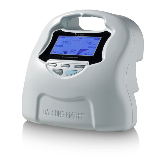
The Venous Assist System
User Manual
This product is medical device using under doctor's instructions.
Indications for Safety Use
Read this manual carefully. This manual is for user's safety and preventing
any property-loss. Before using our device, please read this manual inevitably.
www.dsmaref.com
Advertisement
Table of Contents

Related Manuals for DAESUNG MAREF DVT-2600


Summary of Contents for DAESUNG MAREF DVT-2600
-
Page 1: User Manual
The Venous Assist System User Manual This product is medical device using under doctor's instructions. Indications for Safety Use Read this manual carefully. This manual is for user's safety and preventing any property-loss. Before using our device, please read this manual inevitably. www.dsmaref.com... -
Page 2: Operation Of The Controller
The DVT-2600 has an integrated self-checking system which includes checks for the digital sensor, cuff connection, and power supply. If an error code shows during initial operation of the DVT-2600, it can be checked against the error code key attached to the side of the DVT-2600 unit for convenient reference. - Page 3 2.2 Precautions - If any pain or oedema occurs during use of the device, cease therapy and seek medical advice. - Use caution with the device on patients with any prosthesis inserted. - Assess skin integrity frequently during use in patients with diabetes or vascular disease.
-
Page 4: Weee Marking
Business users should contact their supplier and check the items and conditions of the purchase contract. This product should not be mixed with other commercial waste for disposal. DVT-2600... -
Page 5: Product Description
3. Product Description 3.1 Summary and Specifications Composition - The controller - Air connectable hose - AC power cord Operating principle The operating principle is that the air from the controller will be delivered to the cuff with 3 air chambers and the air will sequentially pressurize the chambers from 1st to 3rd. -
Page 6: Name Of Each Part
(ex. 40 → 50 → 60 → 20 → 30 → 40mmHg). The LCD screen will remain turned off if the user does not apply the cuff, as the controller automatically selects the cuff when the START/STOP button is selected. DVT-2600... - Page 7 The controller has an automatic gradient pressure application which applies gradient pressure into each chamber of a cuff sequentially (+/- 5mmHg). For cuffs with 3 chambers such as the leg/calf/boot cuff; if 40mmHg is set, pressure will be delivered as 35/40/45mmHg to the three chambers. 2.
- Page 8 START/STOP button during the error mark on the screen. 6. LCD display screen 1) Batteries status indicator DVT-2600 is equipped with a battery pack as standard. There are four battery status indicator LED's used to represent the charge level of the battery. 2) AC power indicator AC power indicator (LED) represents one of power input or the fail of power input.
- Page 9 4) Battery charging To charge the batteries, please ensure the device is plugged in and the device power switch is on. The amount of power the batteries can deliver will vary according to a battery’s condition and the settings of the device. Regular battery charging time is approximately 4 hours.
-
Page 10: Operating Mode
Interval time will start after pressurisation of both legs. Foot cuff Leg cuff <Picture 2> 3) Interval Mode After initial pressurisation, the interval time setting on the LCD (counter) will decrease gradually and will restart the pressurisation cycle at the end of the interval time. DVT-2600... -
Page 11: Error Description
(3) Error Description If there is an error with the controller; the error mode will start with an alarm. The controller will revert back to Waiting Mode when the user presses START/STOP. > Error Mode Segment Segment Error information Error information Vent error Pressure in cuff doesn't ventilate. - Page 12 - During the initial self detection test, if the pump is not operating normally, Error code 32 will be displayed. *Checking points ① Check pump operation after opening the cover of the controller ② Check the wire connection in the controller. DVT-2600...
-
Page 13: System Description
- Code 42 is displayed when there is a problem with the power supply generated by the inner batteries. Please call your local representative. 3.3 System description (1) Main compositions 1) DVT-2600 controller Voltage and AC power ● : 100-200V~, 50/60Hz Power consumption : 25W(35VA) ●... - Page 14 2) DVT-2600 Accessories >Single use cuff Cuff Size Width Code Non woven Soft fabric Small 60cm DS011 / DS211 Medium 75cm DS012 / DS212 Thigh cuff Large 93cm DS013 / DS213 X-Large 113cm DS014 / DS214 Small 50cm DS021 / DS221...
- Page 15 (2) Cuff usage and caution 1) Two cuffs + Controller Controller Two connectable hoses Two same cuffs Two different cuffs 2) One cuff + Controller Controller One connectable hose One cuff (3) Cuff usage and caution 1) Do not turn on the power switch before applying cuff(s) to a patient. Connect the hoses after the cuffs are applied to the patient.
-
Page 16: Controller Views
100-240V~, 50/60Hz Power consumption 25W(35VA) Air power consumption below 5W Noise level Above 2 KV Operation nose level below 60dB Max. pressure level 140mmHg Controller weight Controller size 200(W) x 165(D) x 190(H) mm 3.6 Products Label (1) Copyright DVT-2600... - Page 17 (2) Label Caution BF type medical equipment Europe certificate mark Manufacturer mark Service supplier mark Production date LOT NO Serial No. <Products information sticker> This label is attached on the rear of a controller. ※ DS MAREF...
-
Page 18: Product Composition
4. Product composition 4.1 Package DVT-2600 consists of a controller box and a cuff box. The contents of each box are described below. (1) Controller A. DVT-2600 main body B. The form for shock prevention of the controller C. Connectable hose D. -
Page 19: Other Points To Note
F. User manual for cuffs G. Cuff package pack Check point of normal products A. Products model name (DVT-2600) B. Cuff size and material C. The right connection of a hose socket and outlet of a controller D. The right connection of a hose socket and outlet of a cuff hose E. -
Page 20: Setup And Use
6) The controller will operate automatically utilizing the entered settings after the cuff self-test operation. 7) Press and hold the START/STOP button for 3 sec to stop therapy. Check therapy parameters are in accordance with medical supervision. 8) Start the operation. DVT-2600... - Page 21 5) Temporary numbness or Irritation caused by the cuff. 5.4 Setting and use As DVT-2600 is a medical device for the purpose of assisting with venous therapy, DVT- 2600 is to be used only under medical supervision. The device is not recommended for long term use.
-
Page 22: Maintenance
Do not open the cover of the battery pack or tamper with it in any way. (fire or explosion risk) Dispose of the battery properly according to local regulation. The warranty period for the battery is 6 months after the date of purchase. DVT-2600... -
Page 23: Troubleshooting
7. Troubleshooting 7.1 Troubleshooting Condition Cause Solution Power connection Check that the plug is correctly No electric power error inserted into the power outlet Power on but Turn power to the controller off Power supply error not operating and on Check that the device is installed horizontally Noisy during... - Page 24 Defect of Inner parts of cuff Power on but Defect of Inner Check that the plug is correctly not operating parts inserted into the outlet Manufacturer is not responsible for any defect incurred by user neglect. ※ DVT-2600...
- Page 25 8. Schematics 1) Parts Assembly Diagram : SUB-ASM-FORNT Name FRONT_COVER (1EA) KNOB_BUTTON (1EA) SUB_BOARD_KEY (1EA) M3XL6 TT (8EA) WASHER (2EA) MAIN_BOARD_LCD (1EA) WINDOW_SHEET (1EA) 2) Parts Assembly Diagram : SUB-ASM-FRAME Name FRAME_MAIN (1EA) SHEET_PLATE (1EA) COVER_PLUG (2EA) RUBBER_HOSE_ELBOW (6EA) SOLENOID (2EA) RUBBER_HOSE_CONNECTOR (1EA) RUBBER_HOSE_PRESSURE (70mm) M3XL5S (8EA)
- Page 26 3) Parts Assembly Diagram : SUB-ASM-REAR Name REAR_COVER (1EA) RUBBER_PAD (2EA) SUB_BOARD_CHARGE (1EA) AC_INLET (1EA) 4) Parts Assembly Diagram : SUB-DVT-2600 Name SUB_ASM_FRONT M3XL6 TT (9EA) SUB_ASM_FRAME SUB_ASM_REAR SMPS (1EA) M3XL5 S (2EA) M3XL8 TT (8EA) BATTERY (1EA) CAB_BATTERY (1EA)
-
Page 27: Warranty
Warranty We appreciate your use of our device. Daesung Maref will continue to improve the quality of our products. We will not be responsible for any defect incurred due to neglect by ※ the user or any of the following: 1. - Page 28 Success Design product 2003 FDA in USA 2002 ISO9001/EN13485 2002 CE marks (DL series, MK series, DL1200, DVT-2600) 1986 DS MAREF is established 689-31, Geumjung-dong, Gunpo-shi, Geonggi-do, 435-862, Korea Tel : +82-31-459-7211 Fax : +82-31-459-7215 E-mail : ds@dsmaref.com http://www.dsmaref.com EC Representative Supply...
Need help?
Do you have a question about the DVT-2600 and is the answer not in the manual?
Questions and answers