Table of Contents
Advertisement
T
-
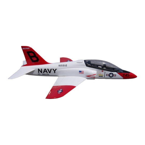
45 Goshawk Composite V2
T
-
45 Goshawk Composite V2
Specifications
Material:
Length:
Wing Span:
Wing Area:
All Up Weight:
Wing Loading:
EDF:
Recommended Motor:
Recommended ESC:
Recommended Battery:
Radio System:
The World's Finest Electric Aircraft
Assembly Manual
Assembly Manual
Composite Fuselage, Balsa Wings
39.3 in
37.4 in
1.937 ft²
54 - 65 oz
27 - 33 oz/ft²
70mm with 5 Blade Fan
2842MB1 @ 3200KV (1100W)
80A+
LiPo, 4s 3300 - 3700 mAH
4 - 6 Channel (optional retracts)
www.SapacAmerica.com
Advertisement
Table of Contents

Related Manuals for Sapac T-45 Goshawk Composite V2

Summary of Contents for Sapac T-45 Goshawk Composite V2
- Page 1 45 Goshawk Composite V2 45 Goshawk Composite V2 Assembly Manual Assembly Manual Specifications Material: Composite Fuselage, Balsa Wings Length: 39.3 in Wing Span: 37.4 in Wing Area: 1.937 ft² All Up Weight: 54 - 65 oz Wing Loading: 27 - 33 oz/ft² EDF: 70mm with 5 Blade Fan Recommended Motor:...
- Page 2 IN ANY WAY CONNECTED WITH THE PRODUCT, WHETHER SUCH CLAIM IS BASED IN CONTRACT, WARRANTY, NEGLIGENCE, OR STRICT LIABILITY. Further, in no event shall the liability of Sapac exceed the individual price of the Product on which liability is asserted. As Sapac has no control over use, setup, final assembly, modification or misuse, no liability shall be assumed nor accepted for any resulting damage or injury.
-
Page 3: Table Of Contents
§ Table of Contents What’s in the Box ....................1 Airframe Components ......................1 Additional Kit Components ....................1 Main Hardware Bag Contents [H1]..................2 Thrust Duct & Elevator Hardware Bag Contents [H2]............... 2 Additional Required Components ................... 3 Available Optional Components ..................... 3 Assembly Sequence .................... - Page 4 § Table of Contents Make Control Rod....................... 29 Nose Wheel Final Assembly ....................30 Nose Wheel, Retractable (Optional) ............... 31 Cut Opening in Fuselage for Nose Wheel ................31 Mount Nose Gear Retract Unit ..................... 32 Mount Strut and Test Retract Motion..................33 Mount Steering Servo ......................
-
Page 5: What's In The Box
§ What’s in the Box ’ ’ Airframe Components Additional Kit Components } } } } } } } } The following are the main airframe components The following are the additional components of the T-45. included with the T-45 Kit. Additional kit components Airframe components o o o o H1... -
Page 6: Main Hardware Bag Contents [H1]
§ What’s in the Box Main Hardware Bag Contents [H1] Thrust Duct & Elevator Hardware Bag Contents [H2] } } } } The following are the components packed in the Main Hardware Bag [H1]: } } } } The following are the components packed in the Thrust Duct &... -
Page 7: Additional Required Components
} } } } The following is the list of additional To complete your T-45, the following components required to complete and fly your components are recommended by SAPAC as T-45: they are designed to work seamlessly with this model. -
Page 8: Assembly Sequence
§ Assembly Sequence Assembly sequence for SAPAC T-45 Goshawk Composite V2 T-45 Goshawk Composite... -
Page 9: Wing Control Surfaces
§ Wing Control Surfaces By using thin CA you will make sure that the Hinge Wing Control Surfaces glue is wicked up the complete surface of the Required Parts hinge for a tighter bond. Avoid the use of o o o o Wing [W] accelerator in this joint since you don’t want to cure the adhesive before it completely coats the... -
Page 10: Cut Servo Slots In Wing
§ Cut Servo Slots in Wing } } } } Using a sharp hobby knife, trim away the covering from the servo arm slots in the servo Required Parts covers o o o o Wing [W] o o o o Servo Covers (4) [W3] Required Tools and Adhesives ®... -
Page 11: Mount Aileron And Flap Servos To Servo Covers
§ Mount Aileron and Flap Servos to Servo Covers Required Parts o o o o Wing [W] o o o o Servo Covers (4) [W3] o o o o Servo Mounting Posts (8) [W3] o o o o Flap Servos (2) + Hardware o o o o Aileron Servos (2) + Hardware Required Tools and Adhesives... -
Page 12: Bond And Mount Control Horns
§ Bond and Mount Control Horns Route Servo Wires Required Parts Required Parts o o o o o o o o Wing [W] Wing [W] o o o o o o o o Aileron Control Horns (4) [W4] Aileron Servo Assembles (2) [W3] o o o o Flap Control Horns (4) [W4] o o o o... -
Page 13: Make Control Rods And Mount Servos
§ Make Control Rods and Mount } } } } Tip, when using servo extensions or Y-harnesses Servos that will be buried inside the wing it is highly recommended that you use extension safety Required Parts clips (or equivalent alternative) to secure them. o o o o Wing [W] This will prevent servo wires coming undone... - Page 14 § Completed control rod assembly } } } } Once you have completed the mounting of the flaps make sure they are in the completely retracted position as you will use them as a reference for centering the ailerons when creating the aileron control rods.
-
Page 15: Main Gear, Fixed (Optional)
§ Main Gear, Fixed (Optional) Build Gear Mounts Cut Slots in Wing for Gear Mounts Required Parts Required Parts o o o o o o o o Main Gear Central Mounts (2) [W5] Wing [W] o o o o o o o o Main Gear Side Components (4) [W5] Main Gear Cover (for measuring) [W5] Required Tools and Adhesives... -
Page 16: Prepare Gear Mount Covers
§ Main Gear, Fixed (Optional) Prepare Gear Mount Covers Required Parts o o o o Main Gear Mount Assemblies (2) [W5] o o o o Main Gear Covers (2) [W5] o o o o Main Gear Struts [W5] Required Tools and Adhesives ®... -
Page 17: Bond Main Gear
§ Main Gear, Fixed (Optional) Bond Main Gear } } } } Remove the covers and gear struts. Reinforce the pilot holes with thin CA adhesive. Required Parts } } } } Enlarge the holes in the gear covers to o o o o Wing [W] accommodate the gear cover screws. -
Page 18: Main Gear Final Assembly
§ Main Gear, Fixed (Optional) Main Gear Final Assembly Required Parts o o o o Wing [W] o o o o Main Gear Struts (2) [W5] o o o o Main Gear Covers (2) [W5] o o o o Main Gear Cover Screws(8) [W5] o o o o Main Gear Tires (2) [T] o o o o... -
Page 19: Main Gear, Retractable (Optional)
§ Main Gear, Retractable (Optional) Select Retractable Gear Strut Geometry Required Parts o o o o Main Gear Retract Template Required Tools and Adhesives ® ® ® ® Scissors ® ® ® ® Hobby Knife Straight strut cutout geometry option A } } } } Before cutting the openings in the wing for the retractable landing gear you need to determine... -
Page 20: Cut Openings In Wing For Mounts And Gear
§ Main Gear, Retractable (Optional) Cut Openings in Wing for Mounts and Gear Required Parts o o o o Wing [W] o o o o Main Gear Retract Template Required Tools and Adhesives ® ® ® ® Hobby Knife ® ® ® ® Fixed gear strut cutout geometry ®... -
Page 21: Mount Gear
§ Main Gear, Retractable (Optional) Mount Gear Required Parts o o o o Wing [W] o o o o Main Retractable Landing Gear Units (2) Retract Unit Mounting Screws (8) o o o o Required Tools and Adhesives ® ® ® ® Hand Drill Completed retractable gear opening cutout ®... -
Page 22: Route And Connect Air Lines
§ Main Gear, Retractable (Optional) Route and Connect Air Lines Final Assembly Required Parts Required Parts o o o o o o o o Wing [W] Wing [W] o o o o Air Line o o o o Main Wheels [T] Air Line T-Fitting o o o o o o o o... -
Page 23: Wing Belly Pan
§ Wing Belly Pan Fit Wing Bolt Reinforcement Trim and Fit Belly Pan Required Parts Required Parts o o o o o o o o Wing [W] Wing [W] o o o o o o o o Wing Mounting Hardware [W2] Wing Mounting Hardware [W2] o o o o o o o o... -
Page 24: Trim Wing Covering
§ Wing Belly Pan } } } } Once you are happy with the fit of the belly pan Trim Wing Covering draw lines along the edges. This will denote the location where the covering will be removed Required Parts from the wing to expose the wood for bonding o o o o Wing [W]... -
Page 25: Bond Wing Bolt Reinforcement Plate
§ Wing Belly Pan } } } } Once the glue is dry place the washers in Bond Wing Bolt Reinforcement position and hold them in place with a drop of Plate thin CA adhesive. Required Parts o o o o Wing [W] o o o o Wing Mounting Hardware [W2]... -
Page 26: Bond Belly Pan
§ Wing Belly Pan Bond Belly Pan Required Parts o o o o Wing [W] o o o o Main Fuselage [F] o o o o Wing Belly Pan [W1] Required Tools and Adhesives ® ® ® ® Thick CA Adhesive ®... -
Page 27: Rudder Modification (Optional)
§ Rudder Modification (Optional) Separate Rudder from Fuselage Reinforce Rudder Required Parts Required Parts o o o o o o o o Fuselage [F] Rudder [F] o o o o Rudder option wooden elements [F2] Required Tools and Adhesives ® ® ® ® Required Tools and Adhesives Sharp Hobby Knife, Hobby Saw or Small Rotary Cutter... -
Page 28: Mount Rudder Servo
§ Rudder Modification (Optional) Mount Rudder Servo Required Parts o o o o Fuselage [F] o o o o Rudder Servo + Hardware Long Servo Extension o o o o Required Tools and Adhesives ® ® ® ® ® ® ® ® Sharp Hobby Knife, Hobby Saw or Small Rotary Cutter Rudder spine bonded in place, note bevel and taper... -
Page 29: Reinforce Vertical Stabilizer
§ Rudder Modification (Optional) Reinforce Vertical Stabilizer } } } } Tip, use a piece of masking tape or painters tape to mark the location of the slot and to cut Required Parts out the slot, this will make marking easier and o o o o Fuselage [F] will protect the fiberglass gel coat from... -
Page 30: Hinge Rudder And Mount Control Horn
§ Rudder Modification (Optional) Hinge Rudder and Mount Control Horn Required Parts o o o o Fuselage [F] o o o o Rudder [F] o o o o Hinges (2) [F4] o o o o Control Horn Install the control horn Required Tools and Adhesives ®... -
Page 31: Make Control Rod
§ Rudder Modification (Optional) Make Control Rod Required Parts o o o o Fuselage [F] o o o o Control Rod Control Rod Keeper (or equivalent) o o o o Required Tools and Adhesives ® ® ® ® Needle Nose Pliers ®... -
Page 32: Nose Wheel, Fixed (Optional)
§ Nose Wheel, Fixed (Optional) steering arm flush with in the top of the strut Mount Nose Wheel Strut and at the desired angle. Use thread locking Required Parts compound to ensure the steering arm does not o o o o Fuselage [F] come loose. -
Page 33: Mount Steering Servo
§ Nose Wheel, Fixed (Optional) Mount Steering Servo Make Control Rod Required Parts Required Parts o o o o o o o o Fuselage [F] Fuselage [F] o o o o Nose Wheel Servo + Hardware o o o o Fixed Landing Gear Hardware, Nose [F1] Linkage Stopper (Optional) o o o o... - Page 34 § Nose Wheel, Fixed (Optional) Nose Wheel Final Assembly Required Parts o o o o Fuselage [F] o o o o Fixed Landing Gear Hardware, Nose [F1] o o o o Wheels & Tires [T] Required Tools and Adhesives ® ® ® ® Hex Wrench ®...
- Page 35 § Nose Wheel, Retractable (Optional) Cut Opening in Fuselage for Nose Wheel Required Parts o o o o Fuselage [F] o o o o Nose Gear Retract Template Required Tools and Adhesives ® ® ® ® Removable Tape Nose wheel cutout complete ®...
Need help?
Do you have a question about the T-45 Goshawk Composite V2 and is the answer not in the manual?
Questions and answers