
Related Manuals for AcSiP S76S


Summary of Contents for AcSiP S76S
- Page 1 S76S/S78S SDK Manual Document Name S76S/S78S SDK Manual Version Doc No Date May 3, 2017 Document History Revised Versi Date Revised Contents S76S/S78S SDK Manual Product Name Version Doc No May 3, 2017 Date 0 of 33 Page...
- Page 2 2017 FTP information removed Tseng May 3, 2017 Tseng Index 1. Overview 2. Hardware Interface 2.1 Connections between MCU & SX1276 2.2 Pin definition S76S/S78S SDK Manual Product Name Version Doc No May 3, 2017 Date 1 of 33 Page...
- Page 3 5.2.1 Flow Chart of Main C Source Code 6. LoRaWAN deployment ™ 6.1 What’s LoRaWAN ™ 6.2 LoRaWAN Open Source 6.3 LoRaMac-node works with S76S/S78S SDK LoRa Driver S76S/S78S SDK Manual Product Name Version Doc No May 3, 2017 Date...
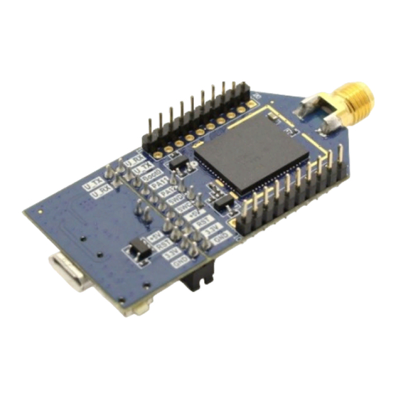
- Page 4 1. Overview The S76S/S78S is designed & manufactured in a smallest form factor - SiP ( System in Package ). It integrates with Semtech SX1276/SX1278 and a 32-bit ultra-low power Coretex®-M0+ MCU (STM32L073x), supporting global 868 MHz or 915 MHz ISM-Bands/433 MHz ISM-Bands. Capable of 2- way communication and reach over 16 km (10 miles) distance in our field test.
- Page 5 Figure 1.1 (Take S76S as example) Figure 1.2 S76S Block Diagram Figure 1.3 S78S Block Diagram S76S/S78S SDK Manual Product Name Version Doc No May 3, 2017 Date 4 of 33 Page...
-
Page 6: Hardware Interface
As the figure 2.2 tells, STM32L073X MCU and SX1276 are packaged as SiP (System in Package) and named as S76S/S78S which is located in the center of the EK-S76SXB/EK-S78SXB board (the center part of figure 2.2). 2.2 Pins definition 2.2.1 XB board Peripheral List... - Page 7 Up to 42 Mbps, it can either configure as Master or Slave mode. ADC pins 12-bit ADC in. VCC & GND pins Test pins for measuring purpose. S76S/S78S SDK Manual Product Name Version Doc No May 3, 2017...
- Page 8 PB0 for ADC pin24 PB0_IO_INT1 PB1 for ADC/I2C2 SDA pin25 PB1_IO_INT2 pin26 pin27 pin28 PC9 for DAC/I2C3 SDA pin29 RXTX Switch pin30 RXTX/RFMOD S76S/S78S SDK Manual Product Name Version Doc No May 3, 2017 Date 7 of 33 Page...
- Page 9 (up to 1MHz). and it support DMA mode to reduce CPU overload. 2.3.3 VDD33 A 3.3V pin that is provided by a 5V-to-3V regulator (LDO), and it provides the power supply to MCU and SX1276. S76S/S78S SDK Manual Product Name Version Doc No...
- Page 10 The detailed reference about SPI is located in this below link: http://www.st.com/content/ccc/resource/technical/document/reference_ manual/2f/b9/c6/34/28/29/42/d2/DM00095744.pdf/files/DM00095744.pdf/jc r:content/translations/en.DM00095744.pdf Chapter 31 Serial peripheral interface/ inter-IC sound (SPI/I2S) 2.3.8 NRST S76S/S78S SDK Manual Product Name Version Doc No May 3, 2017 Date 9 of 33...
- Page 11 NRST can trigger an external reset to MCU system reset when V NRST low. A system reset sets all registers to their reset values except for the RTC, RTC backup registers and control/status registers. S76S/S78S SDK Manual Product Name Version...
-
Page 12: Upgrade Firmware
ST Link Pin9 <==> SWCLK on XB board ST Link Pin12 <==> GND on XB board ST Link Pin1 <==> ST Link Pin19 S76S/S78S SDK Manual Product Name Version Doc No May 3, 2017 Date 11 of 33... -
Page 13: Software Preparation
Figure 3.4 3.1.2.1 STM32 ST-LINK/V2 USB Driver Installation Install ST-LINK/V2 USB Driver for PC/NB. Connect to www.st.com. In the search tab, part number, look for ST-LINK/V2. S76S/S78S SDK Manual Product Name Version Doc No May 3, 2017 Date... - Page 14 STM32 ST-LINK Utility. If HW & SW installation completes, connection would be establish after click “connect” button. Figure 3.5 3.2.2 Disconnect ST-LINK click “disconnect” button after program is done S76S/S78S SDK Manual Product Name Version Doc No May 3, 2017 Date...
- Page 15 2) Select a hex file and click on the Open button. Figure 3.7 3) Specify the address from which to start programming as shown in Figure 3.8, it may be a Flash or RAM address. (Optional) S76S/S78S SDK Manual Product Name Version...
- Page 16 USB Port x 2 on PC/NB site ULINK2 unit x1 EK-S76SXB/EK-S78SXB board x1 Mini USB cable x 1 and Micro USB cable x1 S76S/S78S SDK Manual Product Name Version Doc No May 3, 2017 Date 15 of 33...
- Page 17 cable. (See Figure 3.9) 3.4.2 Software Preparation Please follow chapter 4.1 to complete KEIL installation first. 3.5 Connection & Disconnection via ULINK2 3.5.1 Setup debugger as ULINK2 S76S/S78S SDK Manual Product Name Version Doc No May 3, 2017 Date...
- Page 18 After finishing KEIL installation, open an AcSiP’s SDK project named “Ping-Pong-L0.uvprojx” in this path “\Keil\AcsipNode\ping-pong\” by launching uVision5 and looks similar to the picture below (see Figure 3.13). Figure 3.13 Over the position “Ping-Pong-L0” and press right button of you mouse.
-
Page 19: Developer Environment
Cortex-M processor based microcontroller devices. The Pack Installer manages Software Packs that can be added any time to MDK Core. This makes new device support and middleware updates independent from the toolchain. S76S/S78S SDK Manual Product Name Version... -
Page 20: Installation
Install MDK legacy MDK Version 5 is capable of using MDK Version 4 projects after installation of the Legacy Support from www.keil.com/mdk5/legacy, please download “legacy support for Cortex-M devices Version 5.17” S76S/S78S SDK Manual Product Name Version Doc No... - Page 21 EK-S76SXB/EK-S78SXB board is using this type, STM32L073RZ. We can update the related packs from “Device\ All Devices\ STMicroelectronics\ STM32L0 Series\ STM32L073\ STM32L073RZ\ STM32L073RZHx” as Figure 4.4. Please press the buttons to let them update. S76S/S78S SDK Manual Product Name Version Doc No...
- Page 22 Figure 4.4 4.2 Set-up (Only for ST-LINK/V2) Open AcSiP’s SDK project in this path “\Keil\AcsipNode\ping- pong\Ping-Pong-L0.uvprojx” (Explain how to download in following chapter) by launching uVision5 and looks similar to the picture below (Figure 4.5). S76S/S78S SDK Manual Product Name...
- Page 23 192kB Flash” in the dialog just like the below Figure 4.7. Figure 4.7 4.3 Edit Source and Build When uVision5 start and loads with the correct setting mentioned above, we can load AcSiP SDK project and do some action of what you want. S76S/S78S SDK Manual Product...
- Page 24 Run the application on the target hardware using ST-Link debugger. Click Run on the debug toolbar to start executing the SDK. The detailed information of this chapter can be checked from the below link: http://www2.keil.com/docs/default-source/default-document- library/mdk5-getting-started.pdf?sfvrsn=2[NC,L] S76S/S78S SDK Manual Product Name Version Doc No May 3, 2017 Date...
- Page 25 USB interface to get UART1 log data, to know the current RSSI and SNR value when executing Ping-Pong. a. While a S76S/S78S XB board boots up, it will enter ping-pong master mode by default. Therefore, one of two devices would send “Ping”...
-
Page 26: Power Saving
“Pong” signal after it receives “Ping” signal as Figure 5.4. Figure 5.4 Eventually, the two S76S/S78S XB board devices can communicate each other and shows RSSI and SNR information on PC/NB terminal by USB interface (transferred from UART). (See Figure 5.5) Figure 5.5... -
Page 27: Flow Chart
2.7uA. (The UART-To-USB IC and 5V-To-3V LDO IC are not considered into.) 5.2 Flow Chart 5.2.1 Flow Chart of Main C Source Code The below flow chart describes when S76S/S78S boots up, it goes through several feature and loops in ping pong mode. S76S/S78S SDK Manual Product... - Page 28 Figure 5.7 Figure 5.8 describes all function blocks inside S76S/S78S SDK. It simply divides as three main featured layers: Application layer, S76S/S78S SDK and S76S/S78S HW. The mentioned LoRa Ping-Pong behavior is located in Application layer in “main.c”. Users can start to customize their own behavior on this layer like some commands that can interact with external interface (like UART), or start to receive/send sensor data for collection or calculation.
- Page 29 Figure 5.8 S76S/S78S SDK Manual Product Name Version Doc No May 3, 2017 Date 28 of 33 Page...
- Page 30 LoRaWAN protocol for improving battery of life, better security and effective management. User can utilize AcSiP S76S/S78S SDK MCU & SX1276 ready LoRa® drivers, to develop & customize their own commands and LoRaWAN protocol by different regional radiation rules. 6.1 What’s LoRaWAN LoRaWAN™...
- Page 31 In “Keil” folder, it contains all related uVision (Keil) workable project files. From the top of either S76S/78S SDK project or LoRaMac-node project, it always starts from Application layer, so user can execute customized peripheral behavior like LoRa ping-pong or simple sensor read/write data in main.c (inside src/app folders).
Need help?
Do you have a question about the S76S and is the answer not in the manual?
Questions and answers