
Related Manuals for Clear Comfort CCW100


Summary of Contents for Clear Comfort CCW100
- Page 1 Clear Comfort Residential Pool & Spa Sanitation System Installation, Operations & Maintenance Manual IMPORTANT SAFETY INSTRUCTIONS For further assistance contact us: 303.872.4477 support@clearcomfort.com clearcomfort.com...
- Page 2 For the latest version, please visit: clearcomfort.com/residential-manual MADE IN USA © 2019 Clear Comfort. All Rights Reserved.
-
Page 3: Table Of Contents
Important Safety Instructions ..........3 Electrical Safety ..............4 Grounding ................4 General Safety ............... 4 System Description for Standard Clear Comfort Systems ..5 Key Features ................5 Operating Ranges and Technical Specifications ....5 Light Functionality ..............6 Installing the Clear Comfort System ........ -
Page 5: Warranty
To obtain warranty replacements or and service. Clear Comfort, LLC at repair, defective components or parts its discretion may repair or replace should be returned, transportation the Equipment or parts thereof. -
Page 6: General Information
GENERAL INFORMATION IMPORTANT SAFETY INSTRUCTIONS 1. READ AND FOLLOW ALL of electric shock, replace damaged INSTRUCTIONS. cord immediately. 2. For cord connected/convertible 8. For units intended for above units: DANGER – Risk of injury. ground storable swimming pools: WARNING – To reduce the risk of A. -
Page 7: Electrical Safety
Protect the power cord from electrical code. GROUNDING being walked on or pinched, particularly at plugs and the The Clear Comfort, LLC system point where they exit from the must be properly grounded. An system. electrical ground connection to a •... -
Page 8: System Description For Standard Clear Comfort Systems
KEY FEATURES This manual describes how to install, operate and maintain the standard Clear Comfort system. The installation takes only a few hours and can be installed with little or no disruption to a facility’s recirculation or electrical systems. The Clear Comfort system immediately starts to work... -
Page 9: Light Functionality
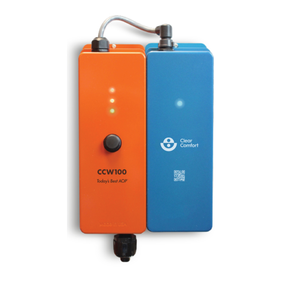
SYSTEM DESCRIPTION FOR STANDARD CLEAR COMFORT SYSTEMS FRONT VIEW Red LED Yellow LED Blue LED Green LED System Power Switch Control Unit Cartridge Unit Figure 1: System Functions LIGHT FUNCTIONALITY Green Light: System is on and operating properly. Yellow Light: Cartridge has reached 80 percent of its life expectancy (8,000 hours) and it’s time to purchase a replacement cartridge. -
Page 10: Installing The Clear Comfort System
Indoors or outdoors: Either is suitable. Install away from upward • facing sprinklers is recommended. Water quality at installation: The water quality should be • balanced prior to installing the Clear Comfort system. CLEAR COMFORT STANDARD INSTALLATION KIT 1. Venturi 2. Air Check Valve 3. 10’ Tubing 4. -
Page 11: System Installation
ELECTRICAL INSTALLATION - GENERAL 1. Follow all local and national electric codes. 2. Determine if the Clear Comfort system will be powered by 120V or 230V. NOTE: All units are factory set to 230V. 3. Set the switch on the ballast... -
Page 12: Electrical Installation - Directly To Pump Circuit
ELECTRICAL INSTALLATION - WALL OUTLET 1. If the unit is being wired to standalone 120V AC power (i.e., not through the pump circuit), connect Clear Comfort system to the pool timing clock so that the system operates simultaneously with pool pump through a Ground Fault Circuit Interrupt (GFCI). -
Page 13: Cartridge Connection
INSTALLING THE CLEAR COMFORT SYSTEM CARTRIDGE CONNECTION Gently align the notched outdent on the front of the Cable Connector with the keyed indent of the front of Cartridge Connector, as shown with the arrow in Figure 3. Seat the Cable Connector down onto the Cartridge Connector and turn the Cable Connector’s Collar a quarter-turn clockwise... -
Page 14: Installing The Clear Comfort Injection Assembly
7. Set venturi air suction to draw between 5 - 7 LPM using a flow meter. Refer to page 14 for detailed instructions. NOTE: For full system diagrams that include additional sanitation systems integrated with the Clear Comfort system, see pages 16, 17 and 18. Figure 4: Full System Diagram With U-Bypass Injection (PREFERRED METHOD) 303.872.4477... -
Page 15: Suggested Minimum Parts
INSTALLING THE CLEAR COMFORT INJECTION ASSEMBLY SUGGESTED MINIMUM PARTS LIST FOR U-BYPASS INJECTION CONNECTING CLEAR COMFORT SYSTEM TO VENTURI INJECTION Water Flow Figure 5: Venturi Connection NOTE: Air Check Valve should be installed to flow in a vertical, downward direction below the exit from the system. - Page 16 3. Install 1⁄4-inch one-way air check valve (supplied) to eliminate any potential water back flow. See Figure 5. 4. Gas exiting the Clear Comfort system to the venturi connector port should flow easily. 5. Measure air suction using an air flow meter and set venturi air suction to draw between 5 - 7 LPM.
-
Page 17: Airflow Meter
INSTALLING THE CLEAR COMFORT INJECTION ASSEMBLY From CCW100 System To Venturi FLOW Figure 9: 1/4” One-Way Air Check Valve AIR FLOW METER 1. Determine your variable speed setting and run your pump (2,400 RPM or higher). 2. Disconnect the blue hose below the check valve. See Figure 10 below. -
Page 18: Operating Instructions
5. To increase the draw of air from venturi system, adjust or slowly close bypass 3-way port valve. 6. Toggle Clear Comfort system switch to the ON position. 7. Water entering the pool/spa should have bubbles exiting from at least one of the returns on to the body of water. -
Page 19: Full System Integration Diagrams
FULL SYSTEM INTEGRATION DIAGRAMS FULL SYSTEM DIAGRAM: AUTOMATIC CHLORINE FEEDER CCW100 1.5” Union Meter Tubing Venturi Check Valve Feeder Input Heater Filter Feeder 3-Way Output Port Valve Chlorine Pool Feeder Pump Figure 13: Automatic Chlorine Feeder FULL SYSTEM DIAGRAM: INLINE CHLORINE FEEDER... -
Page 20: Offline Chlorine Feeder Diagram
FULL SYSTEM INTEGRATION DIAGRAMS FULL SYSTEM DIAGRAM: OFFLINE CHLORINE FEEDER CCW100 1.5” Union Venturi Tubing Check Valve Heater Filter 3-Way Port Valve Chlorine Pool Feeder Pump Figure 15: Offline Chlorine Feeder FULL SYSTEM DIAGRAM: SALT WATER CHLORINE GENERATOR CCW100 1.5”... -
Page 21: Uv System Diagram
FULL SYSTEM INTEGRATION DIAGRAMS FULL SYSTEM DIAGRAM: UV SYSTEM CCW100 1.5” Union Venturi Tubing Check Valve Heater Filter 3-Way Port Valve Pool UV System Pump Figure 17: UV System 303.872.4477 support@clearcomfort.com clearcomfort.com... -
Page 22: System Maintenance
SYSTEM MAINTENANCE CARTRIDGE REPLACEMENT The Cartridge Unit must be replaced annually. No other maintenance is required. If the yellow OR red LED light is illuminated, the cartridge must be replaced. 1. Turn off and disconnect power to Clear Comfort system. Never attempt to service unit while it is wet. - Page 23 SYSTEM MAINTENANCE 4. Remove Cartridge Unit from Control Unit. Note: Please return old cartridge to Clear Comfort for proper recycling. For sustainability purposes, Clear Comfort provides a return-shipping label so the cartridge can be properly recycled. 5. To install the replacement cartridge,...
-
Page 24: Frequently Asked Questions
• Where does the Clear Comfort system get installed? The Clear Comfort system needs to be within 10 feet of the pool or spa venturi injection site. It can be installed either indoors (as long as there is access for the air handling) or outdoors on the pool or spa. -
Page 25: Wiring
For questions regarding this operational mode please contact Clear Comfort at 303.872.4477. 230V power supply cord supplied and must be field wired in accordance to the NEC (ONLY FOR 230V). -
Page 26: Appendix
T-fitting (not supplied)- this allows the addition of ambient air to the flow of oxygen from the OG-20 concentrator. Connect a second port of a T-fitting to the Clear Comfort system using supplied blue tubing. The third port of the T-fitting should remain open to allow ambient air to combine with oxygen from the OG-20 concentrator pulled into the Clear Comfort system. - Page 28 For the latest version, please visit: clearcomfort.com/residential-manual For further assistance contact us: 303.872.4477 support@clearcomfort.com clearcomfort.com MADE IN USA © 2019 Clear Comfort. All Rights Reserved.
Need help?
Do you have a question about the CCW100 and is the answer not in the manual?
Questions and answers