Beastx MICROBEAST PLUS Quick Start Manual
6-axis mems sensor system for rc-models
Hide thumbs
Also See for MICROBEAST PLUS:
- Quick start manual (29 pages) ,
- Manual (353 pages) ,
- Quick start manual (30 pages)
Table of Contents
Advertisement
Quick Links
Advertisement
Table of Contents

Related Manuals for Beastx MICROBEAST PLUS


Summary of Contents for Beastx MICROBEAST PLUS
- Page 1 Version 4.1 QUICKSTART GUIDE...
- Page 2 STUDIOX.BEASTX.COM BEASTX.COM WIKI.BEASTX.COM 1016...
-
Page 3: Safety Notes
Never fly in the rain or extremely high humidity. • When operating the helicopter with a MICROBEAST PLUS ensure there is a sufficiently large and stable receiver power supply. Because of the direct coupling of the rotor blades to the servos, without the use of a flybar mixer, the servos are exposed to increased actuating forces. - Page 4 • When operating the RPM Governor feature of MICROBEAST PLUS it is essential to ensure that the motor cannot start by accident when making adjustment or performing preparations to start the engine. Carefully read this manual and make sure you fully understand how the RPM Governor feature is operated before making any adjustments.
- Page 5 MICROBEAST PLUS is a high-end flybarless system for RC helicopters that has been developed in Germany using latest technology and setting high standards. This system can be used with nearly any size and type of RC helicopters and besides using it as flybarless stabilization system it offers additional features that can make flying helis even easier and comfortable.
-
Page 6: Hardware Installation
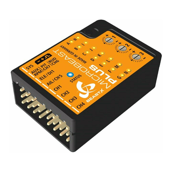
1. HARDWARE INSTALLATION You can position MICROBEAST PLUS flat or upright on the helicopter. The large socket must point to the front or to the rear of the helicopter. The small white socket must be aligned with the longitudinal axis. -
Page 7: Connecting The Receiver
The additional supply cables may be connected to free receiver ports. We recommend to use MICROBEAST PLUS HD... - Page 8 DSMX remote satellite push and hold the button and turn on power while still holding the button down. The LED on the sa- tellite will flash together with Menu LED H on the MICROBEAST PLUS. When binding a DSM2 remote satellite do not touch the button but only power on the device.
- Page 9 4. PREPARING YOUR TRANSMITTER Create a new helicopter model memory in your transmitter that supplies different flight modes for controling throttle, pitch and the tail gyro gain in different flight situations. You must not use any mixing functions on the output channels! Especially it is not allowed to use mixing functions for the swashplate servos.
-
Page 10: Receiver Setup
5. RECEIVER SETUP To enter Receiver menu MICROBEAST PLUS must be switched off completely. Push and hold the button before and while powering on. Menu LED A will start to flash instantly. At menu point A choose which type of receiver/transmission protocol is used. The color and state of the Status LED indicates which type is currently selected. - Page 11 Auxiliary (CH6) Auxiliary (CH6) When using SRXL the preset channel assignment is based on the receiver‘s protocol version. MICROBEAST PLUS will detect automati- cally which brand of receiver is used and will choose the appropriate channel assignment accordingly. * Channel designation of Spektrum® transmitters: THR, AIL, ELE, RUD, GER, PIT, AX2, AX3, AX4...
-
Page 12: Setup-Menü
6. SETUPMENÜ Self test Switch on transmitter Switch on Status LED lights up power supply red->blue->purple Calibration of Calibration of sensor Firmware version: 4.1.x Operation mode radio channels rest positions Do not move sticks on Do not move the Status LED lights up the radio! helicopter! blue... - Page 13 If you don‘t know what the maximum update rate that is tolerated by your servos never use more than 50Hz. The higher the update rate the better it is for the flight performance of MICROBEAST PLUS but you must check the servo specifications before increasing the update rate.
- Page 14 Setup menu point E - Rudder servo limit Plug the rudder servo connector into CH4 output of MICROBEAST PLUS. Put the servo arm on the servo so that it forms roughly an angle of 90 degrees with the rudder linkage rod and adjust the length of the linkage rod as described in the helicopter manual.
- Page 15 Setup menu point F - Tail gyro direction Lift the helicopter at the rotorhead and turn it on the vertical axis by hand. Observe in which direction the rudder servo moves the tail rotor when turning the heli. The tail rotor must produce thrust against the direction of movement so that the rotation will be stopped by the gyro in flight.
- Page 16 By moving the rudder stick into one direction repeatedly select one servo after another and adjust each servo‘s center position by moving the elevator stick forwards or backwards so that the servo arm is positioned exactly 90 degrees to the linkage rod. The servo number that is currently selected and that can be trimmed at the moment is indicated by the Status LED color.
- Page 17 Do not use the servo reverse function of MICROBEAST PLUS to change stick directions! When the swashplate can be controlled as expected briefly push the button to skip to menu point J.
- Page 18 Setup menu point J - Swashplate servo throw Align rotorhead and rotorblades in parallel to the helicopter‘s longitudinal axis. Attach a pitch gauge/level meter to one of the rotor blades or to a blade grip in order to measure aileron pitch. 0°...
- Page 19 Setup menu point L - Swashplate servo limit You can remove the pitch gauge now! Simultaneously move the sticks for thrust, aileron and elevator to the maximum deflection and check if the servos, swashplate or linkages get jammed in a certain position. By pushing and holding the rudder stick left or right you can increase or decrease the limit for the servos! Adjust the limit so that the servos just don‘t get jammed in any possible stick position but don‘t limit the servos more than necessary.
- Page 20 When you‘re using the RPM Governor of MICROBEAST PLUS now connect the RPM sensor (i. e. magnetical, optical or brushless phase sensor) or the wire for RPM signal of your ESC to the white sensorport on the long side. For this you may need the optional available BXA76401 adapter.
- Page 21 7. GOVERNOR SETUP MENU Governor menu point A - Test mode (Menu LED A flashing slowly) If the RPM Governor was activated at Setup menu point N (setting „electric“ or „nitro/gas“ heli) you will access the Governor menu immediately afterwards. At menu point A we check if the rpm sensor is functioning properly and if the rpm sensor wire is connected correctly.
- Page 22 Governor menu point B - Motor off/Idle position Using an electric heli move the throttle to the position at which the motor is just before to start running, i.e. by adding throttle until the motor starts to turn and then reducing the throttle a little. With a nitro/gas heli move the throttle to a stable idle position.
- Page 23 Manual control Idle up Autorotation 100% • Throttle in idle • Range between • Throttle set between 1800rpm position 0% und 50% 50% and 100% • When switching back equals headspeed of directly controls to idle up (>50%) 600 - 3000rpm the throttle servo motor will restart •...
- Page 24 The best way is to give a fair and direct collective pitch input to lift the helicopter quickly up into the air. Adjusting the three dials on top of MICROBEAST PLUS you can optimize the control loop and customize it to your helicopter.
-
Page 25: Parameter Menu
The Parameter menu allows you to further customize the flight characteristics of the helicopter and the reaction of the system to control inputs. You can find a detailed description for each parameter in the MICROBEAST PLUS instruction manual. Entering Parameter menu... - Page 26 10. ATTITUDECONTROL (OPTIONAL) Parameter menu point L - AttitudeControl mode AttitudeControl can be used to level the helicopter automatically by the flip of a switch. This provides different applications i.e. to use as bail out rescue in case the pilot looses orientation, to have a training aid for learning new flight maneuvers or to use as stabilization for camera flights.
- Page 27 When activating AttitudeControl you should be able to see an immediate impact on the swashplate control: If the heli is tilted to one side, MICROBEAST PLUS permanently steers the swashplate opposed to the inclination. In the region around horizontal position the swashplate will always stay nearly horizontal to the ground.
-
Page 28: Menu Overview
FIRMWARE VERSION 4.1 MENU OVERVIEW WWW.BEASTX.COM SETUP MENU flashing flashing flashing flashing purple blue (Menu LED solid) purple blue red/blue horizontal vertical hor. inv. vert. inv. horizontal vertical hor. inv. vert. inv. Device orientation socket in front socket in front... - Page 29 PARAMETER MENU flashing flashing flashing purple blue (Menu LED flashing quickly) purple blue Swashplate quick trim / Use aileron and elevator stick to trim, hold button 2s to trim rudder. Reset all by rudder stick input. AttitudeControl trim Switch trim mode by activating AttitudeControl using the AttitudeControl switch channel. Control style User defined normal...
-
Page 30: Declaration Of Conformity
We are not responsible for any damage which occurs as a result of these contents.. Do not hesitate to send us any suggestions for improvement by e-mail to info@beastx.com. This product contains chemicals known to the State of California to cause cancer, birth defects or other reproductive harm.
Need help?
Do you have a question about the MICROBEAST PLUS and is the answer not in the manual?
Questions and answers