
Related Manuals for King Industrial KC-235PM


Summary of Contents for King Industrial KC-235PM
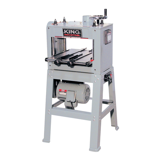
- Page 1 13” PLANER/MOULDER INSTRUCTION MANUAL MODEL: KC-235PM COPYRIGHT © 2002 ALL RIGHTS RESERVED BY KING CANADA TOOLS INC.
- Page 2 IMPORTANT INFORMATION 2-YEAR KING CANADA TOOLS LIMITED WARRANTY OFFERS A 2-YEAR LIMITED WARANTY FOR INDUSTRIAL USE. FOR THIS PLANER / MOULDER PROOF OF PURCHASE Please keep your dated proof of purchase for warranty and servicing purposes. REPLACEMENT PARTS Replacement parts for this tool are available at our authorized KING CANADA service centers across Canada. For servicing, contact or return to the retailer where you purchased your product along with your proof of purchase.
-
Page 3: General Safety Instructions For Power Tools
GENERAL & SPECIFIC SAFETY INSTRUCTIONS VOLTAGE WARNING: Before connecting the tool to a power source (receptacle, outlet, etc.) be sure the voltage supplied is the same as that specified on the nameplate of the tool. A power source with voltage greater than that for the specified tool can result in SERIOUS INJURY to the user - as well as damage to the tool. -
Page 4: Table Of Contents
TABLE OF CONTENTS & SPECIFICATIONS TABLE OF CONTENTS General safety instructions for power tools ............................3 Specific Safety Instructions ................................3 Table of contents....................................4 Specifications ....................................4 Loose Parts Bag ....................................5 Getting to know your planer/moulder ..............................5 Mounting on a stand/mounting motor ..............................6 Belt Tension Adjustment ..................................7 ON/OFF Switch ....................................7 Removing Planer Knives ..................................8... -
Page 5: Loose Parts Bag
LOOSE PARTS BAG & GETTING TO KNOW YOUR PLANER/MOULDER LOOSE PARTS BAG 1) Knife setting gauge ..................1pc 2) Knife setting gauge shaft ................1pc 3) Gib knock shaft (bronze) ................1pc 4) Base locking screws ..................4pcs 5) Handwheel fixing screw ................1pc Dust hood lock screw ..................3pcs 6) Table raising handwheel ................1pc 7) Speed change gear ................(57 T, 20 T) -
Page 6: Mounting On A Stand/Mounting Motor
MOUNTING ONTO STAND & MOUNTING MOTOR MOUNTING PLANER ONTO THE STAND Assemble stand and place the planer onto the top of the stand and firmly bolt together with the four cap screws. CAUTION! To place the planer into the stand, you will need the assistance of another person. -
Page 7: Belt Tension Adjustment
BELT TENSION ADJUSTMENT ON/OFF SWITCH BELT TENSION ADJUSTMENT If this is the first time you install and/or adjust the belts and the belt tension, begin by placing the belts around the two pulleys. Place a straight edge against both pulleys and check to make sure they are both aligned with eachother. -
Page 8: Removing Planer Knives
REMOVING PLANER KNIVES & KNIFE SETTING REMOVING PLANER KNIVES Unplug your planer from it's power source. CAUTION! Always unplug your planer from it's power source before changing knives and molding bits. Your planer Knives are held in position by wedge action. The gib fixing screws press against the bottom of the cutterhead slot forcing the gibs into a wedge-type seal. -
Page 9: Installing Moulding Cutter Bits
INSTALLATION & ALIGNMENT OF MOULDING CUTTER BITS INSTALLATION OF MOULDING CUTTER BITS Moulding cutter bits fit directly into the center of each cutterhead slot and can be used with the planer blades so that you can actually plane and mould in one pass. The planer/moulder accepts two thicknesses of cutter: 3,8 mm and 6.3 mm. -
Page 10: Adjusting The Depth Of Cut Scale
ADJUSTING THE DEPTH OF CUT SCALE, DEPTH OF CUT & TABLE GUIDES ADJUSTING THE DEPTH OF CUT SCALE TABLE RAISING HANDWHEEL For safe operation of your planer/moulder, it is very important that the depth of cut scale is read accurately. To adjust the depth of cut scale, follow the steps outlined below: CAUTION! Unplug your planer/moulder from its power source. -
Page 11: Installing Bedboard
INSTALLING BEDBOARD & DUST COLLECTOR DUST CHUTE INSTALLING BEDBOARD The moulding knives are made so the extreme cutting tips can cut into the wood bedboard. This is necessary to eliminate rough edges and for final sizing. Always use a bedboard so the knives do not come into contact with the cast iron bed of your planer/moulder. -
Page 12: Chip Guide Plate Adjustment
CHIP GUIDE PLATE ADJUSTMENT, SHARPENING AND RECOMMENDED KNIFE ANGLES CHIP GUIDE PLATE ADJUSTMENT Before planing, adjust the chip guide plate so that there is a clearance of 1.0 - 1.5 mm between the guide plate and the planer knife tip. CAUTION! When moulding, be sure to move the chip guide plate away to prevent it from being hit by the moulding cutter. -
Page 13: Changing Feed Speed
CHANGING FEED SPEED & FEED ROLLER ADJUSTMENT CHANGING FEED SPEED The planer/moulder has a 2 speed gearbox that feeds the workpiece at 10 feet per minute (FPM) for improved surface finish when moulding and 20 FPM for faster planing. CAUTION! Be sure to unplug the planer/moulder and turn it OFF before changing the gear. -
Page 14: Making The Cutterhead And Worktable Parallel
MAKING THE CUTTERHEAD AND WORKTABLE PARALLEL MAKING THE CUTTERHEAD AND WORKTABLE PARALLEL Plane a workpiece and measure the workpiece thickness after the cut. If the thickness is not the same on both sides of the workpiece, perform the following: Adjust the cutterhead and the worktable so they are parallel. The tools used for checking are shown below. -
Page 15: Thickness Planing Steps
THICKNESS PLANNING STEPS PLANING FOR FINISH THICKNESS PLANING STEPS To properly use your planer/moulder for thickness planing, follow the steps below: 1) Measure the thickness part of the board to be planed. Turn the table raising hand lever until the scale depth of cut reads the thickness of the board to be planed. -
Page 16: Planing For Finish
MAINTENANCE & TROUBLESHOOTING PERIODIC MAINTENANCE Buildup of sawdust and other debris can cause your machine to plane and mould inaccurately. Periodic cleaning and waxing is not only recommended, but mandatory for accurate precision planing and moulding. 1) Close-fitting parts, such as gibs and the planer cutterhead slots should also be wiped with an oily cloth and freed from clinging foreign matter and then replaced in their respective positions, slightly dampened with oil. -
Page 17: Troubleshooting
TROUBLESHOOTING Board thickness doesn't Depth of cut scale incorrect. Adjust depth of cut scale. match depth of cut scale. Chain jumping. 1. Inadequate tension. 1. Adjust chain tension. 2. Sprockets misaligned. 2. Align sprockets. 3. Sprockets worn. 3. Replace sprockets. M e c h a n i c a l / e l e c t r i c a l 1.
Need help?
Do you have a question about the KC-235PM and is the answer not in the manual?
Questions and answers