
Related Manuals for King Industrial KC-240M


Summary of Contents for King Industrial KC-240M
- Page 1 7” industrial planer/moulder 04/2017 instruCtion manual model: KC-240m COPYRIGHT © 2016 ALL RIGHTS RESERVED BY KING CANADA TOOLS INC.
-
Page 2: Warranty Information
WarrantY inFormation 2-Year KinG Canada tools limited WarrantY oFFers a 2-Year limited WarrantY For tHis 7” plner/moulder For CommerCial use. prooF oF purCHase Please keep your dated proof of purchase for warranty and servicing purposes. replaCement parts Replacement parts for this product are available at our authorized King Canada service centres across Canada. limited tool WarrantY King Canada makes every effort to ensure that this product meets high quality and durability standards. -
Page 3: General Safety Instructions
General saFetY instruCtions VoltaGe WarninG: Before connecting the machine to a power source (receptacle, outlet, etc.) be sure the voltage supplied is the same as that specified on the nameplate. A power source with voltage greater than specified can result in SERIOUS INJURY to the user - as well as damage the machine. -
Page 4: Electrical Information
eleCtriCal inFormation WarninG ALL ELECTRICAL CONNECTIONS MUST BE DONE BY A QUALIFIED ELECTRICIAN. FAILURE TO COMPLY MAY RESULT IN SERIOUS INJURY! ALL ADJUSTMENTS OR REPAIRS MUST BE DONE WITH THE MACHINE DISCONNECTED FROM THE POWER SOURCE. FAILURE TO COMPLY MAY RESULT IN SERIOUS INJURY! poWer supplY starting and stopping the automatic feed rollers WarninG: YOUR PLANER/MOULDER MUST BE CONNECTED TO... -
Page 5: Specifications
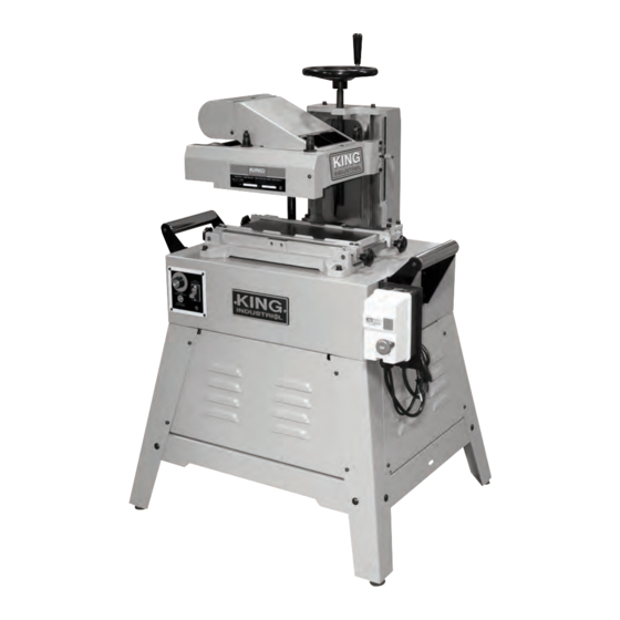
12. Variable feed rate control dial 13. Table 14. Feed motor 15. Dust Hood 16. Elliptical jig assembly 17. Elliptical jig mounting bracket speCiFiCations model KC-240m Maximum planing width 7” Maximum moulding width 6-3/4” Maximum thickness of stock 8” Minimum thickness of stock 1/4”... -
Page 6: Assembly And Setup
assemblY & setup installinG tHe CutterHead HeiGHt adJustment HandWHeel To install the cutterhead height adjustment handwheel: 1. Loosen the set screw (A) Fig.4 on the handwheel (B) using a 3mm hex. key so that the handwheel can slide onto the shaft (C). 2. - Page 7 assemblY & setup installinG tHe belt on tHe driVe pulleYs To install the belt on the drive drive pulleys: 1. Using the 6mm hex. key, remove the cap screw and washer (A) Fig.8 which is used to secure the motor during transport. Once the screw has been removed, the motor will swing freely.
-
Page 8: Assembly And Adjustments
assemblY & adJustments installinG leVelinG rubber Feet to tHe stand 1. Install the 4 leveling rubber feet (A) Fig.12 to each stand leg (B) using a washer (C) and two hex. nuts (D) as shown in Fig.12. Adjustments can be made to each leveling rubber foot by loosening the top hex. - Page 9 adJustments inspeCtinG tHe KniVes continued... Warning! Make sure the machine is turned off, and disconnected from the power source. 2. Loosen the three round head allen screws (A) Fig.16, slide and remove the top cover (B) to expose the cutterhead and knives. FiGure 16 3.
- Page 10 adJustments settinG tHe First KniFe parallel to tHe table continued... If the knife is not set parallel to the table: 2. Slowly rotate the upper pulley by hand until the T-handle wrench (A) Fig.20 will fit into the holes in the cutterhead shaft as shown. This will prevent the cutterhead from rotating while adjusting the blade.
- Page 11 adJustments adJustinG tHe HeiGHt oF tHe Feed rollers The feed rollers (A & B) Fig.24 are set at 0.030” below the lowest point of the cutterhead (C) so that they are able to grip the workpiece as it is fed through the machine as shown in Fig.24.
- Page 12 adJustments eXtendinG tHe Feed roller liFe For most moulding cuts, the feed rollers will need to be adjusted. This will depend on the type of moulding cutter being used. When making deeper cuts, or for larger profiles, the height of the feed rollers can be adjusted by turning the screws (B) &...
- Page 13 adJustments installinG mouldinG KniVes continued... 8. Install the moulding knife (A) Fig.31 as close to the center as possible, and fasten the knife in place with two locking bolts through the mounting holes of the moulding knife. Make sure that the moulding knife is flush with the bottom lip of the cutterhead while tightening the bolts.
-
Page 14: Operation
operation operation This machine is designed to remove material from the top surface of a workpiece, to either plane the workpiece down to a desired thickness, or mould the workpiece and apply a specific profile and thickness. For best results, the workpiece must have at least one side that has been machined perfectly flat. - Page 15 operation ConneCtinG to a dust ColleCtor This machine is equipped with a 4” dust chute (A) Fig.37, it is used for connecting to a dust collector. Ensure that the correct size fittings and hose are used to minimize airborne dust. planinG 1.
- Page 16 operation mouldinG CurVed pieCes usinG tHe elliptiCal JiG The elliptical jig allows this machine to handle curved workpieces. To mould curved workpieces, the workpiece is usually secured to a template that rides along the inner and outer guide bearings of the jig as shown in Fig.41. When doing full width profile cuts, the workpiece (A) Fig.41 and template (B) must be the exact same width as the profile (C).
-
Page 17: Operation And Maintenance
operation & maintenanCe mouldinG CurVed pieCes usinG tHe elliptiCal JiG continued... 3. Lower the cuttinghead until it lightly touches the workpiece (A) Fig.45 to align the guide bearings with the cutting knife. 4. Loosen the jam nut (A) Fig.46 on the inner guide, and rotate the adjustment knob (B) until the bearings are aligned with the cutting knife.
Need help?
Do you have a question about the KC-240M and is the answer not in the manual?
Questions and answers