Table of Contents
Advertisement
Quick Links
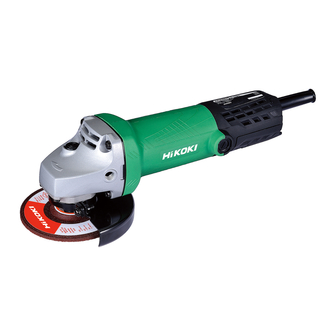
PRODUCT NAME
Hitachi 100 mm Disc Grinder
G 10ST
Model
CONTENTS
PRECAUTIONS IN DISASSEMBLY AND REASSEMBLY ---------------------------------------------- 1
1. Disassembly ------------------------------------------------------------------------------------------- 1
2. Reassembly ------------------------------------------------------------------------------------------- 2
3. Lubrication Points and Types of Lubricant ----------------------------------------------------- 5
4. Tightening Torque ------------------------------------------------------------------------------------ 5
5. Wiring Diagrams -------------------------------------------------------------------------------------- 5
6. Insulation Tests --------------------------------------------------------------------------------------- 6
7. No-Load Current Value ----------------------------------------------------------------------------- 6
STANDARD REPAIR TIME (UNIT) SCHEDULES -------------------------------------------------------------------- 7
LIST No.
G 10ST: F209
Feb. 2011
Page
International Sales Division
G
Advertisement
Table of Contents

Related Manuals for Hitachi G 10ST


Summary of Contents for Hitachi G 10ST
-
Page 1: Table Of Contents
LIST No. G 10ST: F209 Feb. 2011 PRODUCT NAME Hitachi 100 mm Disc Grinder G 10ST Model Page CONTENTS PRECAUTIONS IN DISASSEMBLY AND REASSEMBLY ---------------------------------------------- 1 1. Disassembly ------------------------------------------------------------------------------------------- 1 2. Reassembly ------------------------------------------------------------------------------------------- 2 3. Lubrication Points and Types of Lubricant ----------------------------------------------------- 5 4. -
Page 2: Precautions In Disassembly And Reassembly
1. PRECAUTIONS ON DISASSEMBLY AND REASSEMBLY [Bold] numbers in the descriptions below correspond to item numbers in the Parts List and exploded assembly diagram for the Model G 10ST. 1-1. Disassembly (1) Disassembly of the Armature 1) Remove the Brush Cap [37] and take out the Carbon Brush [38]. -
Page 3: Reassembly
(4) Disassembly of the gear 1) Loosen the four Seal Lock Screws (W/Sp. Washer) M4 x 12 [10] that secure the Packing Gland [9] to the Gear Cover Ass’y [2], and then remove the Packing Gland [9] from the Gear Cover Ass’y [2]. 2) Remove the Retaining Ring For D11 Shaft [3] that secures the gear to the Spindle [12]. - Page 4 (6) Mount the Cord [51] according to the following procedure when replacing the standard cord (with integrally molded cord armor). 1) Remove the standard cord (with integrally molded cord armor) according to the procedure described in 8-1 (3). 2) Strip off about 10 mm of coating from Terminal [44] the tip of the internal wire of the Cord [51], and then crimp the Terminal [44]...
- Page 5 Fig. 6 (9) When replacing the Gear Cover Ass’y [2], lubricate the needle bearing part with mixed oil. Mixed oil: A mixture of Hitachi Power Tool Grease No. 2 (Unilube No. 00, Code No. 939302 recommended) and turbine oil • Mixture ratio ------------------------- 1:1 (weight ratio)
-
Page 6: Lubrication Points And Types Of Lubricant
Generously rub grease onto the gear and pinion. • Needle bearing --------------------------------------- Mixed oil (0.5 cc) Mixed oil: Mixture of Hitachi Power Tool Grease No. 2 (Unilube No. 00, Code No. 939302) and turbine oil Mixture ratio -------------- 1:1 (weight ratio) 1-4. -
Page 7: Insulation Tests
1-6. Insulation Tests Upon completing disassembly and repair, carefully measure the insulation resistance and conduct a dielectric strength test. Insulation resistance: 7 MΩ or more with 500 VDC megohm tester Dielectric strength test: 4,000 VAC/1 minute with no abnormalities ----- 220 to 240 V products 2,500 VAC/1 minute with no abnormalities ----- 110 to 127 V products 1-7. -
Page 8: Standard Repair Time (Unit) Schedules
2. STANDARD REPAIR TIME (UNIT) SCHEDULES Variable MODEL 60 min. Fixed Work Flow Switch Tail Cover (A) Housing Tail Cover (B) Ass'y Cord Stator General Assembly G 10ST Armature Ball Bearing 628VVC2PS2-L Bearing Holder Dust Seal Ball Bearing 626VVC2PS2L Rubber Bushing Packing Gear Cover Ass'y... - Page 9 LIST NO. F209 DISC GRINDER 2011 · 2 · 16 Model G 10ST (E1)
- Page 10 PARTS G 10ST ITEM ITEM CODE NO. CODE NO. DESCRIPTION REMARKS USED USED 320-523 TAPPING SCREW D5 X 25 (BLACK) 316-484 GEAR COVER ASS'Y INCLUD. 5, 20 316-487 RETAINING RING FOR D11 SHAFT 316-486 WAVE WASHER 301-943 LOCK PIN 323-556 SLOTTED HD.
- Page 11 PARTS G 10ST ITEM CODE NO. DESCRIPTION REMARKS USED 994-273 NOISE SUPPRESSOR FOR UAE 930-039 NOISE SUPPRESSOR FOR CHN, KOR, TPE 333-575 TAIL COVER (B) 304-035 TAPPING SCREW (W/FLANGE) D4 X 25 (BLACK) 305-499 MACHINE SCREW (W/WASHER) M3.5 X 6...
- Page 12 STANDARD ACCESSORIES G 10ST ITEM CODE NO. DESCRIPTION REMARKS USED 313-933 WRENCH 320-496 WHEEL WASHER FOR KOR OPTIONAL ACCESSORIES ITEM CODE NO. DESCRIPTION REMARKS USED 314-051 SANDING DISCS 100MM C-P16 (10 PCS.) 314-052 SANDING DISCS 100MM C-P20 (10 PCS.) 314-053 SANDING DISCS 100MM C-P24 (10 PCS.)
Need help?
Do you have a question about the G 10ST and is the answer not in the manual?
Questions and answers