Table of Contents
Advertisement
Quick Links
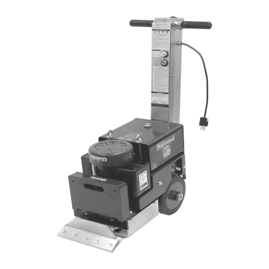
#6280 HYDRAULIC
INSTRUCTION MANUAL
Read Manual Before Operating Machine
National
Carpet Equipment, Inc.
9250 X
A
N
YLON
VENUE
800-245-0267 • 763-535-8206 • F
W
S
: www.nationalequipment.com • E-M
EB
ITE
PANTHER
• M
, MN 55445 • U.S.A.
ORTH
INNEAPOLIS
763-535-8255 • F
AX
®
800-648-7124
AX
: info@nationalequipment.com
AIL
Advertisement
Table of Contents

Related Manuals for National HYDRAULIC PANTHER 6280


Summary of Contents for National HYDRAULIC PANTHER 6280
- Page 1 #6280 HYDRAULIC ® PANTHER INSTRUCTION MANUAL Read Manual Before Operating Machine National Carpet Equipment, Inc. 9250 X • M , MN 55445 • U.S.A. YLON VENUE ORTH INNEAPOLIS 800-245-0267 • 763-535-8206 • F 763-535-8255 • F 800-648-7124 : www.nationalequipment.com • E-M...
-
Page 2: Table Of Contents
6280 TABLE OF CONTENTS Table of Contents ....................2-3 Hydraulic ........................4-5 A. Maintaining A Safe Work Environment ..............4 B. Pressure......................4-5 C. Flammability ......................5 D. Hydraulic Fluid......................5 Rules for Safe Operation..................6-9 A. Grounding ......................8 B. Extension Cords ....................9 Transportation ......................10-11 A. Transport Wheels ....................10 B. - Page 3 6280 TABLE OF CONTENTS Part Numbers and Diagrams................29-36 A. External Parts ....................29 B. Rearview External Parts ..................30 C. Base Plate Parts ....................31 D. Idler Assembly Parts ..................32 E. Pump Drive Assembly Parts ................32 F. Eccentric Assembly Parts ..................32 G. Bearing & Bottom Cover Parts ................32.1 H.
-
Page 4: Maintaining A Safe Work Environment
6280 HYDRAULIC SAFE OPERATION SAFE OPERATION MAINTAINING A SAFE WORK ENVIRONMENT Establishing a safe working environment in and around your hydraulic equipment is just common sense. The easiest and most effective way to avoid problems is to make sure associates understand their equipment, know how to operate it safely and recognize the danger it represents if handled carelessly. -
Page 5: Flammability
6280 HYDRAULIC SAFE OPERATION PRESSURE (continued) 2. Check the threads and/or seat angle for damage that may have occurred prior to or during installation. Any ding or burr may be a potential leak path. Replace if necessary. 3. If the coupling was misaligned during installation, threads may have been damaged. Replace and carefully install. -
Page 6: Rules For Safe Operation
USE” until repaired. A guard or other damaged parts should be properly repaired or replaced. For all repairs, insist on only identical National replacement parts. 11. REMOVE ALL ADJUSTING KEYS AND WRENCHES: Make a habit of checking that the adjusting keys, wrenches, etc. - Page 7 24. MAINTAIN LABELS AND NAMEPLATES: These carry important information. If unreadable or missing, contact National for a free replacement. WARNING: Exposure to dust may cause respiratory ailments. Use approved NIOSH or OSHA respirators, safety glasses or face shields, gloves and protective clothing. Provide adequate ventilation to eliminate dust, or to maintain dust level below the Threshold Limit Value for nuisance dust as classified by OSHA.
-
Page 8: Grounding
6280 RULES FOR SAFE OPERATION GROUNDING WARNING: Improperly connecting the grounding wire can result in the risk of electric shock. Check with a qualified electrician if you are in doubt as to whether the outlet is properly grounded. Do not modify the plug provided with the tool. Never remove the grounding prong from the plug. Do not use the tool if the cord or plug is damaged. -
Page 9: Extension Cords
6280 RULES FOR SAFE OPERATION EXTENSION CORDS WARNING: Electrical cords can be hazardous. Misuse can result in fire or death by electrical shock. Read carefully and follow all directions. Grounded tools require a three wire extension cord. Double insulated tools can use either a two or three wire extension cord. -
Page 10: Transport Wheels
6280 TRANSPORTATION TRANSPORT WHEEL ASSEMBLY • Transport wheels help to eliminate damage to flooring and make movement of unit easier. ATTACHING TRANSPORT WHEELS #6280-301 Front • Remove two outside blade cover bolts (See Figure A). Transport Wheel WARNING: Make sure machine is stable and secure on blocks. - Page 11 6280 TRANSPORTATION Wheels engage and disengage for easier maneuverability. Wheels in the “engage mode” are secured with the axle pins (See Figure A). This engages the wheels for the machine to be self-propelled. When wheels are in the “disengage mode” (See Figure B). Machine can be moved around freely when the machine IS NOT under power.
-
Page 12: Loading
6280 TRANSPORTATION WARNING: When maneuvering machine on any type of a incline (ramp, hill, etc.), wheel engage pins MUST be in place (in engaged mode) (See Figure B) and counterweights removed. LOADING ALWAYS REMOVE ALL COUNTERWEIGHTS AND BLADES BEFORE LOADING OR UNLOADING. LIFTING BAIL •... -
Page 13: Unloading
6280 TRANSPORTATION UNLOADING • Position machine at the back of the truck in line with the ramp (See Figure B). • Carefully move machine onto ramp leaving cutting head down (in contact with ramp surface). WARNING: Ramp must have good contact with the back of the vehicle. Failure to do so could cause ramp to lose contact with back of vehicle resulting in damage to the machine or injury to the operator. -
Page 14: General Operation
6280 GENERAL OPERATION SPECIFICATIONS SPECIFICATIONS #6280 Length: 27.5'' Width: 13'' Height: 41'' Weight (machine only): 360 lbs. Speed: 10 - 45 feet per minute MOTOR INFORMATION RPM: 3450 Volts: 1½ Amps-Full Load: Continuous Duty A well -maintained machine is a productive machine. If not properly maintained, it could be unsafe and could break down. -
Page 15: Maintenance
6280 GENERAL OPERATION MAINTENANCE 1. Always wear eye protection. 2. Keep flammable and fragile objects away from this tool. 3. Always check nuts and bolts to make sure they are tight. 4. Always use the tool with proper voltage specified in the machine’s name plate. 5. -
Page 16: Blades
6280 BLADES BLADE SETTING • Dull blades greatly reduce cutting ability. Re-sharpen or replace as needed. • Proper blade size and placement, depending on material and sub-floor type, affects performance. • The harder a job comes up, for best results, use a smaller blade. •... -
Page 17: Blade Changing
6280 BLADES BLADE SETTING (continued) • Self scoring blades are available in a number of sizes. These blades eliminate the need for pre-scoring material. Depending upon the type of material being removed and the sharpness of the blade and scoring wings, the self scoring blades may make it harder to control the machine. •... -
Page 18: Blade Sharpening
6280 BLADES BLADE SHARPENING • Always wear gloves and safety glasses. • Using hand grinder, block up front of machine so blade is off the floor. • Grind blade using a 4" diameter disk with 120 or finer grit. Be careful not to catch disk on edge or corner of blade. - Page 19 6280 BLADES Double Edge Sharp Blade Support .062 Sharp .062 .094 Heavy Duty .062 .250 Standard Extra Heavy Duty Self-Scoring Corner Swivel Head .187 Attachment .062 SELF SCORING BLADES: Eliminates pre-scoring carpet. See sizes and accessories on Page 17.1. #6253 RIPPER TEETH: Used on real hard to remove goods;...
- Page 20 6280 BLADES Part # Description Application Thickness #130-S 3'' x 10'' Blade with slots Glued down carpet, tile or resilient .062 #130-D #130 Blade with both edges sharpened Carpet, tile or resilient on wood & concrete floors .062 #131-S 3'' x 16'' Blade with slots Glued down rubber carpet, floor accumulation .062 #135...
-
Page 21: Types Of Tearouts
6280 BLADES WARNING: Never remove flooring containing asbestos without fully understanding proper state and federal procedures and guidelines. TYPES OF TEAROUTS REMOVAL MATERIALS • VCT TILE: Never use a blade wider than the size of the tile being Figure A removed (See Figure A). - Page 22 6280 TYPES OF TEAR-OUT TYPES OF TEAROUTS (continued) SUBFLOOR SURFACES • WOOD: When working over plywood sub-flooring, try to run machine in the same direction as the grain in the wood. Blade in most cases bevel down. On solid wood floors like plank, run in the same direction as the plank, not cross grain or cross plank.
-
Page 23: Procedures
6280 PROCEDURES COUNTER WEIGHTS • It is not necessary to have counterweights on to use machine. Use only as needed (See Figure A). • Use 9/16" blade wrench (supplied). Each counterweight is attached with two 3/8" bolts. Remove bolts and counterweights. -
Page 24: Tank Removal
6280 PROCEDURES HYDRAULIC FLUID LEVEL • Machine is run at a low temperature and pressure. • Check fluid level if there has been a leak, damaged or ruptured hose or a loose fitting. Fluid • Fluid level should be higher than the Return Line. See Level Sight Figure A. -
Page 25: Inspection Of Internal Parts
6280 PROCEDURES INSPECTION OF INTERNAL PARTS Visual inspection of internal parts can be done without draining tank. • Remove two lifting bail eyebolts and the two bolts from the back of the tank. • Carefully lift tank 3'' to 4''. •... -
Page 26: Cartridge Replacement
• Reconnect solenoid wires. POWER CORD • If power cord is damaged, it must be replaced by National or its service agent, or a similar qualified person in order to avoid a hazard. ON/OFF SWITCH WIRE DIAGRAM • 2 power wires go to copper spades •... -
Page 27: Troubleshooting
6280 TROUBLESHOOTING IF THERE IS NO FORWARD OR REVERSE: 1. Check speed control valve. Turn counterclockwise to open valve. 2. Check wheel pins. Make sure they are in the wheels. 3. Check belt. Remove front cover plate (#6280-145) and inspect. IF MOTOR SHUTS OFF OR WILL NOT START: 1. - Page 28 Note: Number in parenthesis ( ) is the amount needed on each machine. Parts are sold individually. Be sure to order the number of parts needed.
-
Page 29: Complete Parts List
6280 COMPLETE PARTS LIST PART # DESCRIPTION 6280-6 PUMP SHAFT KEY (NOT SHOWN) 6280-7 TANK MOUNTED STRAINER 6280-103 AXLE SHAFT (OLD STYLE) 6280-103-1 AXLE SHAFT (NEW STYLE) 6280-103A AXLE SNAP RING (2) 6280-104 AXLE SPROCKET WITH KEY 6280-105L AXLE BEARING SUPPORT LEFT 6280-105R AXLE BEARING SUPPORT RIGHT 6280-107... - Page 30 6280 COMPLETE PARTS LIST PARTS (continued) PART # DESCRIPTION 6280-152 MOTOR JUNCTION BOX ONLY 6280-152-1 MOTOR JUNCTION BOX COVER ONLY 6280-152-2 MOTOR JUNCTION BOX & COVER SECURING SCREW (4/BOX, 2/COVER) (NOT SHOWN) 6280-152-3 COVER GASKET ONLY 6280-152-4 JUNCTION BOX FRAME GASKET ONLY 6280-153L LEFT UPPER MAIN BODY 6280-153R...
- Page 31 6280 COMPLETE PARTS LIST PARTS (continued) PART # DESCRIPTION 6280-226 HYDRAULIC MOTOR MOUNTING BRACKET 6280-228 DRIVE CHAIN 6280-229 DRIVE CHAIN MASTER LINK ASSEMBLY 6280-230 SIDE COUNTERWEIGHT RIGHT 6280-231 SIDE COUNTERWEIGHT LEFT 6280-304 DRAIN HOSE 6280-400 ECCENTRIC ONLY (NEED KEY & SET SCREWS) (OLD STYLE) 6280-400A ECCENTRIC ASSEMBLY COMPLETE (OLD STYLE) (INCLUDES 129C, 400, 73010, 73012 [2]) (NOT SHOWN)
- Page 32 6280 COMPLETE PARTS LIST PARTS (continued) PART # DESCRIPTION 73222 3/8-16 X 1 WIZLOCK BOLT ( MOTOR PARTS-2, INTERNAL PARTS-4) 73223 3/8-16 X 1-1/4 WIZLOCK BOLT (MOTOR PARTS-2, INTERNAL PARTS-2) 73224 3/8-16 X 1/2 WIZLOCK BOLT (4) 73226 3/8-24 X 1 HEXHEAD BOLT (4) 73228 3/8-16 X 8 EYEBOLT (2) 73235...
- Page 33 110 VOLT LABEL L95K RAMP LABEL (2) L95L REMOVE COUNTERWEIGHTS LABEL L141 MADE IN USA LABEL L173B STOCK NUMBER LABEL L175 NATIONAL LABEL, SMALL (2) L188 CAUTION GENERAL INFO LABEL L189 SAFE OPERATING TIPS LABEL L223 PATENT NUMBER LABEL Page 28.1...
- Page 34 6280 PART NUMBERS & DIAGRAMS PART # DESCRIPTION EXTERNAL PARTS 6280-110 Wheel Spacer (Not Shown) 6280-111A Wheel Key (Not Shown) 6280-111-2B Wheel with Hub (New Style) 6280-112 Wheel Cap (2) 6280-136 Blade Cover 6280-162 Hydraulic Tank Body 6280-162G Tank Magnet (Not Shown) 6280-163 Hydraulic Tank Cover (Old Style) (Not Shown)
- Page 35 6280 PART NUMBERS & DIAGRAMS REAR VIEW EXTERNAL PARTS 73022 401B 73005 73005 162E 72816 73224 73224 73206 73224 73008 167D 73008 73008 73206 167D 6280-7 PART # DESCRIPTION PART # DESCRIPTION 6280-7 Tank Mounted Strainer 6280-401B Blade Allen Button Head Wrench (New Style) 6280-162E Drain Plug/Oil Level...
- Page 36 6280 PART NUMBERS & DIAGRAMS BASE PLATE PARTS 73217 73211 73205 73211 73205 73211 73205 73205 73201 73211 73211 73204 PART # DESCRIPTION PART # DESCRIPTION 6280-107 Base Plate (2" Eccentric Hole) 73201 3/8-16 x 1 Hexhead Bolt, Grade 5 (4) 6280-108 Base Plate (2¼"...
-
Page 37: Idler Assembly Parts
6280 PART NUMBERS & DIAGRAMS PART # DESCRIPTION IDLER ASSEMBLY PARTS 6280-125 Idler Assembly Complete 73003 (Includes 125A, 126, 126A, 73003, 126A 73218, 73210) (Not Shown) 73218 6280-125A Idler Mounting Bracket & Pin 6280-126A Idler Bearing Cap 71072 Idler Bearing (2) 73003 1/4-20 x 5/8 Button Head Cap Screw 73210... -
Page 38: Bearing & Bottom Cover Parts
6280 PART NUMBERS & DIAGRAMS BEARING & BOTTOM COVER PARTS 71118 73203 73318 132B 73211 71093 6280-138 73318 138E 71118 PART # DESCRIPTION PART # DESCRIPTION 6280-132 Bearing Cup Only (Old Style) 71118 Flange Bearing 6280-132B Cup Bearing w/Bearing Assembly 73203 3/8 Flat Washer (2) (Old Style) -
Page 39: Axle Assembly Parts
6280 PART NUMBERS & DIAGRAMS AXLE ASSEMBLY PARTS PART # DESCRIPTION 6280-103 Axle Shaft (Old Style) 103-1 105R 73311 73310 6280-103-1 Axle Shaft (New Style) 6280-103A Axle Snap Ring (2) 71115 6280-104 Axle Sprocket with Key 103A 6280-105L Axle Bearing Support Left 6280-105R Axle Bearing Support Right 71115... -
Page 40: Internal Handle Parts
6280 PART NUMBERS & DIAGRAMS INTERNAL HANDLE PARTS HOSE PARTS 208A PART # DESCRIPTION 6280-166B Switch Plate Cap 6280-166C Handle Cover Plate 6280-166D Rubber Foam Seal, Large HANDLE PARTS 6280-166E Rubber Foam Seal, Small 6280-167 Handle Body 73002 6280-170 Handle Bar (2) 73019 73019 6280-170A... -
Page 41: Motor Parts
6280 PART NUMBERS & DIAGRAMS MOTOR PARTS BODY PARTS 151B 153L 151A 147-1 153R 73309 73309 73020 148A 73020 155L 73222 152-1 73223 73260 73222 73223 147-3 72364 152-3 72365 152-4 PART # DESCRIPTION PART # DESCRIPTION 6280-152-4 Junction Box Frame Gasket Only 6280-139 Rear Cover 6280-153L... -
Page 42: Switch Parts
6280 PART NUMBERS & DIAGRAMS SWITCH PARTS CUTTING HEAD PARTS 73235 73332 73226 206B 73304 6280-135 71141 161B 161A 161C 161D 62504 PART # DESCRIPTION PART # DESCRIPTION 6280-134 Cutting Head (Old Style) 6280-206 Forward/Reverse Switch (2) 6280-135 Cutting Head Bearing Assembly (Old 6280-206B Switch Cap Style) -
Page 43: Internal Parts Parts
6280 PART NUMBERS & DIAGRAMS INTERNAL PARTS 220A 113S 73222 73223 73223 71115 73204 73206 73204 73203 73204 PART # DESCRIPTION PART # DESCRIPTION 6280-113 Pump Non Spline (Old Style) 6280-225 Hydraulic Motor Spacer 6280-113A Hydraulic Pump Key (Old Style) (Not 6280-226 Hydraulic Motor Mounting Bracket Shown) -
Page 44: Labels
DESCRIPTION Caution Sharp Blade Label (2) L141 Made In USA Label L173B Stock Number Label (2) Power Cord Label L175 National Label, Small (2) L95F Warning Fluid Leak Label L223 Patent Number Label L95H Caution Do Not Run Label L95J... - Page 45 6280 LABELS L95B L189 L95D L95C L95L L188 L95E L95G L95K One label on each side PART # DESCRIPTION PART # DESCRIPTION L95B On/Off Switch Label L95K Ramp Label (2) L95C Forward Label L95L Remove Counterweights Label L95D Reverse Label L188 Caution General Info Label L95E...
-
Page 46: Accessories
6280 ACCESSORIES #6280-500 SWIVEL HEAD ATTACHMENT Unique Swivel Head rotates to use the second sharp edge of the blade without having to remove the blade. Designed to hold razor/scraper blades. Works on thin soft coatings, paint and hard to remove gummy or dry adhesives. -
Page 47: 120 Volt Wiring Diagram
120 VOLT WIRING DIAGRAM Page 39... - Page 48 6280 HYDRAULIC LINE LAYOUT Page 40...
-
Page 49: Material Safety Data
6280 MATERIAL SAFETY DATA Page 41... - Page 50 6280 MATERIAL SAFETY DATA Page 42...
- Page 51 6280 MATERIAL SAFETY DATA Page 43...
- Page 52 6280 MATERIAL SAFETY DATA Page 44...
- Page 53 6280 MATERIAL SAFETY DATA Page 45...
- Page 54 6280 MATERIAL SAFETY DATA Page 46...
-
Page 55: Guarantee
In no event shall National be liable, or in any way responsible for any damage or defects in the product which were caused by repairs or attempted repairs performed by anyone other than National. Nor shall National be liable, or in any way responsible, for any incidental or consequential, economics or property damage. - Page 56 Telephone Number Approximate Usage (hours) Problems Encountered Check One: Repair Do you wish to be contacted before repairing Return Contact National if a loaner is needed Return Authorization Number Date required, contact National Customer Number if known Purchased From if not directly from National...
- Page 57 .062 All orders and payment terms to be verified prior to shipping. National Carpet Equipment, Inc. • 9250 Xylon Avenue N. • Minneapolis, MN 55445 Phone 800-245-0267 or 763-535-8206 • Fax 800-648-7124 or 763-535-8255 Web Site: www.nationalequipment.com • E-Mail: info@nationalequipment.com...